DFD6361-Maintenance.pdf - 第168页
B-96 3-4. Re placing the Spinner T able Safety prec autions for repl acing the spi nner tabl e CAUTION If a scratc hed spinner t able is s et in positi on, the spi nner table flatne ss precision will b e adversely affe c…
B-95
3-3. Changing the Upper Arm Size
Procedures for changing the upper arm size
To change the size of the upper arm, slide the pad plates of the arm to the
position suitable for the frame to be used.
Step No. Do This
(Continued from the previous section)
1
Press the <F1> button from the CHANGE FRAME SIZE screen
[screen 6.1].
- The upper arm then moves to a location above the chuck table.
2
Visually make sure that all drive sections stop completely.
3
Open the front arm section cover.
4
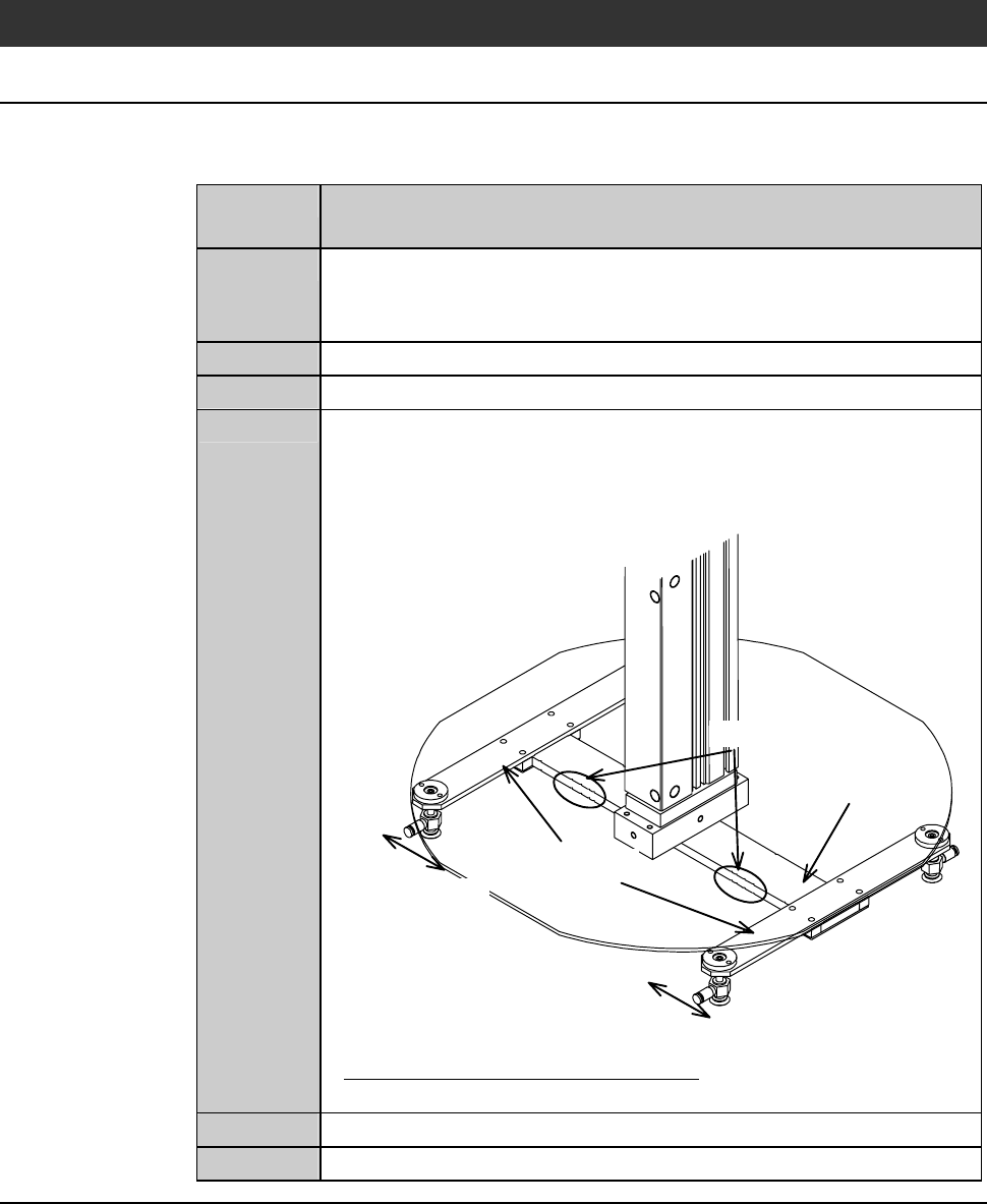
Change the upper arm pad position.
On the arm of the upper arm, there are notches at a number of
places to suit various frame sizes. Slide the pad plates to the
suitable notch for the frame size to be used.
Arm
Notches
Pad plates
Sliding direction
Sliding direction
- About the notch position of the arm;
See the previous section, [Changing the Lower Arm Size].
5
Close the front arm section cover.
6
Press the <System Initial> button to effect system initialization.
Continued in the next section.
B-96
3-4. Replacing the Spinner Table
Safety precautions for replacing the spinner table
CAUTION
If a scratched spinner table is set in position, the spinner table
flatness precision will be adversely affected. Before installing the
spinner table, make sure that the table base and spinner table
surface are not scratched.
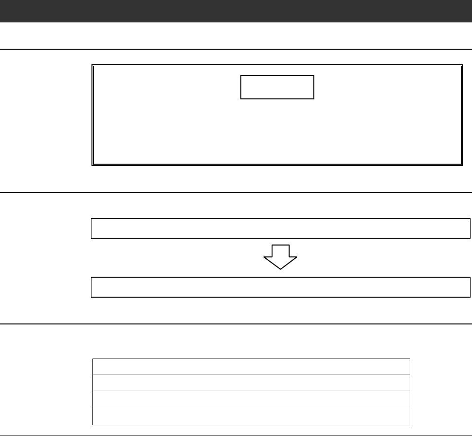
Operation flow
The procedure for replacing the spinner table consists of the following steps.
3-4-1 Removing the spinner table
3-4-2 Mounting the spinner table
Before replacement
Have on hand the followings for replacement of the spinner table.
Alcohol
Lint-free cloth
3 mm Allen wrench (for removing the φ 8" spinner table)
5 mm Allen wrench (for removing the φ 300 mm spinner table)
B-97
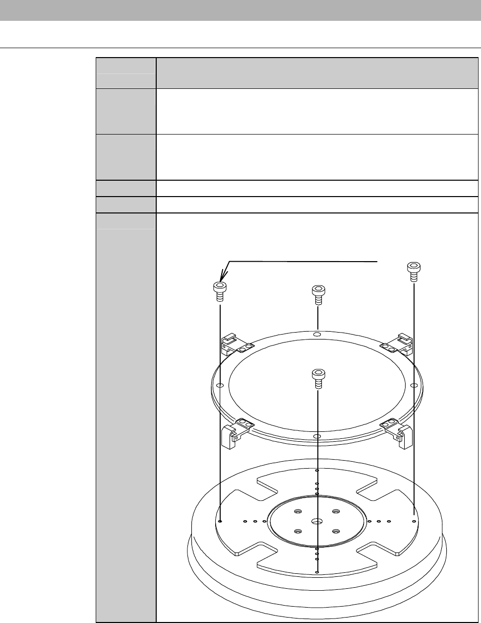
3-4-1. Removing the spinner table
Procedures for removing the spinner table
Step No. Do This
(Continued from the previous section)
1
Press the <F1> button on the CHANGE FRAME SIZE screen
[screen 6.1].
- The upper arm moves to above the chuck table.
2
Press the <F2> button on the CHANGE FRAME SIZE screen
[screen 6.1].
- The lower arm moves to above the chuck table.
3
Visually make sure that all drive sections stop completely.
4
Open the rear arm section cover.
5
Remove the retaining screw of the spinner table.
M4 (for
φ
8" spinner table)
M6 (for
φ
300mm spinner table)