DFD6361-Maintenance.pdf - 第19页
A-3 Machine out er cover configur ation (Conti nued) FRONT SIDE RIG HT SIDE REAR SI DE ÿ LEF T S IDE : Outer c over l ock pos ition
A-2
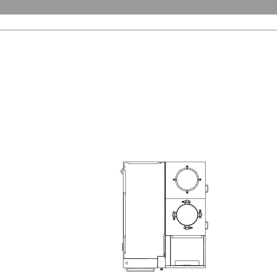
1. Machine Outer Cover
Machine outer cover configuration
The machine outer covers are configured as illustrated below.
Depending on the cover position, the covers are mounted by either of the
following two methods.
- Mounted with the outer cover lock
- Mounted with the mounting screw
To remove the covers mounted with the outer cover lock, you should release
the cover locks which are located at the positions as shown below.
For the procedure to release the cover lock, see [Machine outer cover lock
mechanism] in the next page.
- For the procedure to remove the machine outer cover;
See the section B-2-2, [Removing the Machine Outer Cover and Status
Indicator] of the Installation Manual.
TOP SIDE
A-3
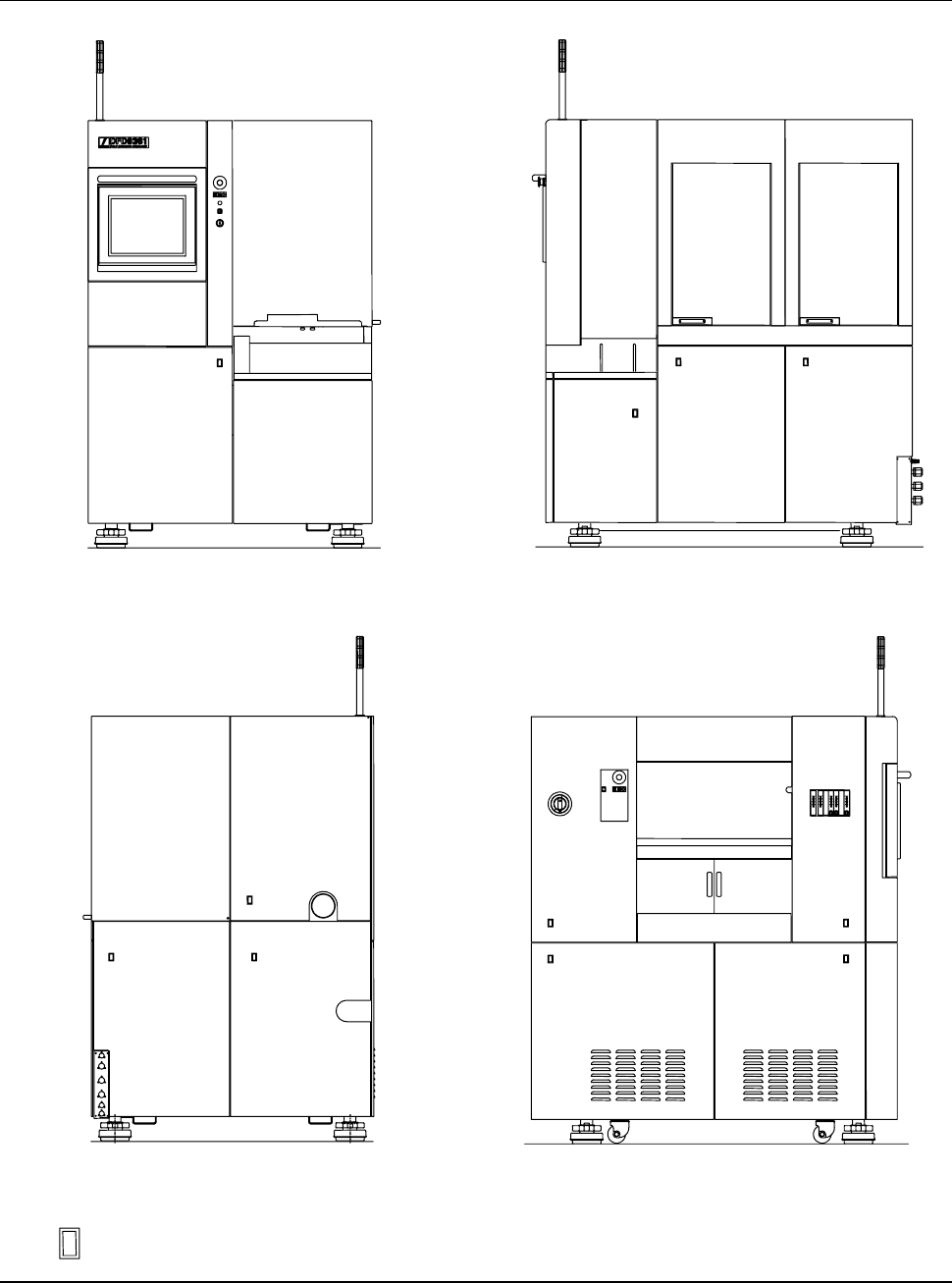
Machine outer cover configuration (Continued)
FRONT SIDE
RIGHT SIDE
REAR SIDE
ÿ
LEFT SIDE
: Outer cover lock position
A-4
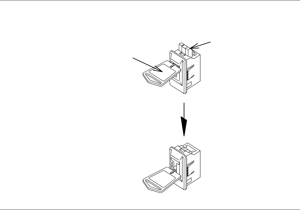
Machine outer cover lock mechanism
To release the cover lock, insert the unlock key into the cover lock section and
unlock the cover as shown below.
Insert the key
and press it down.
Cover lock
Unlock key
Part No. MOHRN001