Infinity EX Transportation.pdf - 第16页
INFINITY EX TRANSPORT ATION MAJOR RE LOCATION 31.1 6 Technical Reference Manual Chapter Issue 3 Jan 04 7. Remov e the right hand machine side cov ers. 8. Disconnect the electrical supply connectors to the pneumatic solen…
INFINITY
EX
TRANSPORTATION
MAJOR RELOCATION
Chapter Issue 3 Jan 04 Technical Reference Manual 31.15
Dismantling To ensure the machine is not damaged during transportation it is recommended
that certain components are removed before dispatch. Remove the following
components:
• Paste dispenser nozzle
• Paste cartridge sleeve
• Paste dispenser drip tray
• Squeegees or ProFlow
• MMI assembly and arm
• Tricolour beacon
• Pneumatic supply fitting
• Magnetic tooling pins
• TCU manifold
• Auxiliary Conveyors (HTC option)
Removal of the
Auxiliary Conveyors
(HTC Option)
To remove the right hand auxiliary conveyor from the machine carry out the
following procedure:
1. Raise the head and insert the head prop.
2. Power down the machine and disconnect the quick release pneumatic con-
nection at the machine’s external services panel.
3. Remove the six pan head M4 securing screws and washers from the front
right hand safety cover and remove the cover from the machine.
4. Remove the six pan head M4 securing screws and washers from the rear right
hand safety cover and remove the safety cover from the machine.
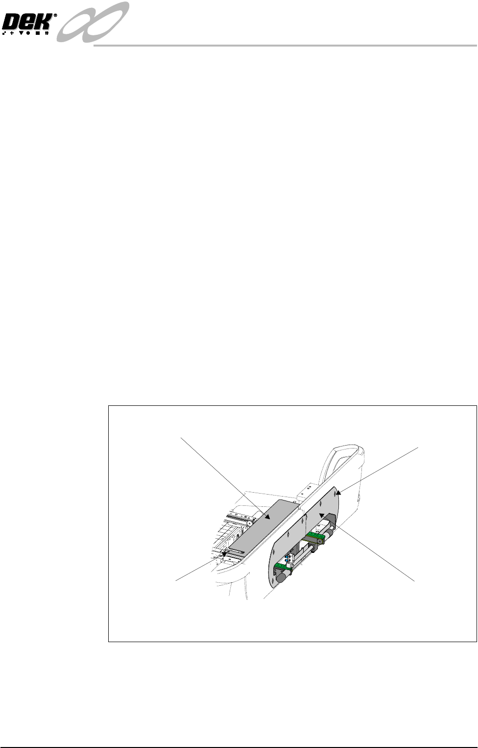
5. Remove the two countersunk M5 screws securing the right hand safety plate
to the green wear insert fitted to the top of the right hand conveyor.
6. Carefully lift the safety plate clear of the machine and remove the two plastic
safety cover spacers from the on top of the green wear insert.
View on Right Hand Side of Machine
M4 Pan Head Screws
(in 6 positions)
Safety Cover
(in 2 positions)
Safety Plate
M5 Countersunk Screw
(in 2 positions)
INFINITY
EX
TRANSPORTATION
MAJOR RELOCATION
31.16 Technical Reference Manual Chapter Issue 3 Jan 04
7. Remove the right hand machine side covers.
8. Disconnect the electrical supply connectors to the pneumatic solenoid valves
M27SOL01 and M27SOL03 fitted to the rear face of the front rail support.
9. Disconnect the pneumatic connection feeding the solenoid valves
M27SOL01 and M27SOL03 at the tee piece connection to valve
M27SOL03.
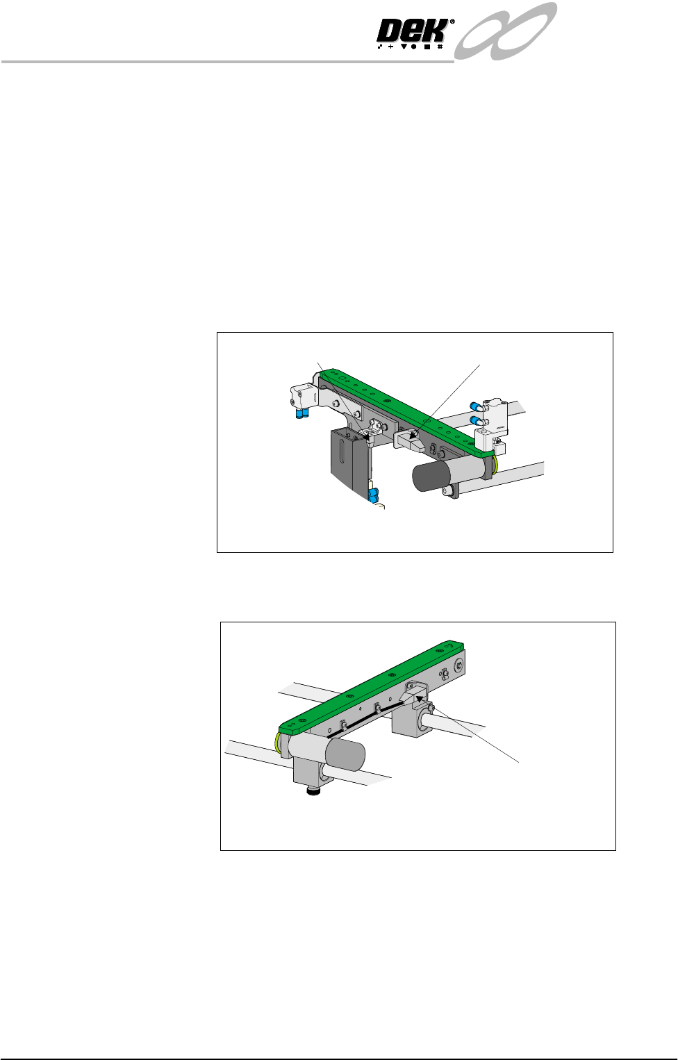
10.Disconnect the following connectors fitted to the front rail of the right hand
auxiliary conveyor:
• M27SK14 - Auxiliary conveyor sensor
• M27PL16 - Auxiliary conveyor front transport belt motor
11.Disconnect connector M27PL17 feeding the auxiliary conveyor rear trans-
port motor, fitted to the rear face of the rear rail of the conveyor.
12.Loosen the eight M5 auxiliary conveyor rail support securing bolts (four
bolts on each support) that secure the auxiliary conveyor to the machine
lower frame.
13.Ensuring the auxiliary conveyor is fully supported, remove the bolts loos-
ened in Step 12 and remove the conveyor from the machine.
14.Refit the right hand machine side panels.
To remove the left hand auxiliary conveyor from the machine carry out the
following procedure:
Front View on Right Hand Auxiliary Conveyor
Connector M27SK14
Connector M27PL16
Connector M27PL17
Rear View on Right Auxiliary Conveyor
INFINITY
EX
TRANSPORTATION
MAJOR RELOCATION
Chapter Issue 3 Jan 04 Technical Reference Manual 31.17
1. Remove the six pan head M4 securing screws and washers from the front left
hand safety cover and remove the cover from the machine.
2. Remove the six pan head M4 securing screws and washers from the rear left
hand safety cover and remove the safety cover from the machine.
3. Remove the two countersunk M5 screws securing the left hand safety plate
to the green wear insert fitted to the top of the left hand conveyor.
4. Carefully lift the safety plate clear of the machine and remove the two plastic
safety cover spacers from the on top of the green wear insert.
5. Remove the left hand machine side covers.
6. Disconnect the electrical supply connector to the pneumatic solenoid valve
M27SOL02 rear face of the front upright of the conveyor frame.
7. Disconnect the pneumatic connection feeding the solenoid valve
M27SOL02.
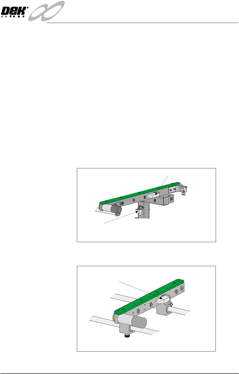
8. Disconnect the following connectors fitted to the front rail of the left hand
auxiliary conveyor:
• M27SK05 - Auxiliary conveyor sensor
• M27PL06 - Auxiliary conveyor front transport belt motor
9. Disconnect connector M27PL07 feeding the auxiliary conveyor rear trans-
port motor, fitted to the rear face of the rear rail of the conveyor.
10.Loosen the eight M5 auxiliary conveyor frame securing bolts (four bolts on
each upright) that secure the auxiliary conveyor to the machine lower frame.
Connector M27SK05
Connector M27PL06
Front View on Left Hand Auxiliary Conveyor
Connector M27PL07
Rear View on Left Hand Auxiliary Conveyor