Infinity EX Transportation.pdf - 第44页
INFINITY EX TRANSPORT ATION MAJOR RE LOCATION 31.4 4 Technical Reference Manual Chapter Issue 3 Jan 04 Figur e 31-11 External Services Item Description 1 6SK13 Host Com ms LAN RJ45 2 Mains Supply 3 Multi-Interface Unit (…
INFINITY
EX
TRANSPORTATION
MAJOR RELOCATION
Chapter Issue 3 Jan 04 Technical Reference Manual 31.43
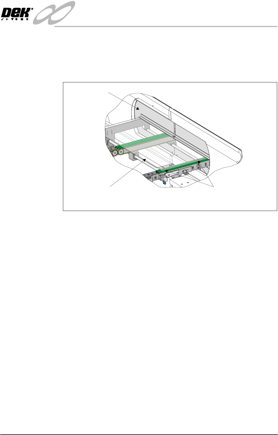
two M5 countersunk screws and nylon spacers. Ensure the spacers are fitted
between the safety plate and the top of the rail.
2. Ensure spacers are fitted to each auxiliary conveyor rear support.
3. Fit the machine safety covers to each side of the machine ensuring the cover
fits over the safety plate preventing it from rising.
External Services In order for the machine to function correctly the following services must be
available. The services must be stable and clean.
Pneumatic Supply The machine requires a pneumatic supply of clean, non lubricated air which
should maintain a minimum pressure 5 Bar and a maximum of 8 Bar.
The air should be to ISO 8573.1 standard, quality class 2.3.3, where:
• 2 dirt = 1 micron
• 3 water = -20°C pressure dewpoint
• 3 oil = 1mg/m
3
Electrical Supply The average power consumption for a machine without any options fitted is
2KVA at 100/240Vac 50/60Hz.
DEK recommends a power supply capacity of 3KVA or greater to accommodate
extra options, surges on power-up and certain machine operations.
CAUTION
OVER CURRENT PROTECTION. Magnetic/thermal over current pro-
tectors protect the machines internal wiring and components from over-
heating/fire during fault conditions. DEK require additional machine
supply protection with the fitment of a wall mounted circuit breaker rated
to 16 Amps and conforming to national/federal regulations.
Safety Cover
(in 2 positions)
Safety Plate
M5 Countersunk Screw
With Spacer (in 2 positions)
Internal View of Right hand Side of Machine
INFINITY
EX
TRANSPORTATION
MAJOR RELOCATION
31.44 Technical Reference Manual Chapter Issue 3 Jan 04
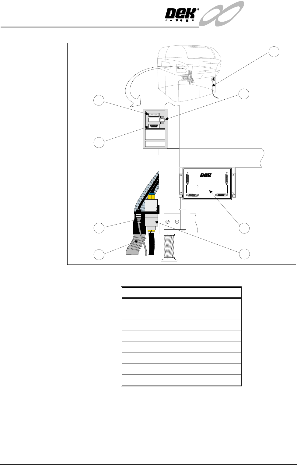
Figure 31-11 External Services
Item Description
1 6SK13 Host Comms LAN RJ45
2 Mains Supply
3 Multi-Interface Unit (optional)
4 Air Connection
5 Vacuum Connection
6 24V Vacuum Control
7 6SK09 Parallel Port Printer
8 FMI Pod (SMEMA interface only)
1
+
2
4
V
+2
4
V
+
2
4
V
(
E
-
S
T
O
P
)
+
2
4
V
(E-
ST
OP)
+
1
2
V
+
1
2
V
+
5
V
+5
V
D
O
W
N
L
I
N
E
R
E
A
D
Y
DO
WNL
INE
RE
A
D
Y
R
S
2
3
2
R
S
2
3
2
D
O
W
N
L
I
N
E
D
OW
N
L
INE
U
P
L
I
N
E
UP
LINE
D
E
K
M
A
C
H
I
N
E
DEK
M
AC
H
INE
U
P
L
I
N
E
R
E
A
D
Y
UPL
I
N
E
RE
ADY
D
O
W
N
L
I
N
E
A
V
A
I
L
A
B
L
E
DO
WN
L
IN
E
A
V
A
I
LAB
LE
S
E
N
D
D
O
W
N
L
I
N
E
S
E
N
D
D
O
W
N
L
INE
S
E
N
D
U
P
L
I
N
E
SEND
U
PLINE
D
E
K
M
/
C
N
A
VA
I
L
A
B
L
E
DE
K
M
/
C
N
A
VA
I
LA
BLE
M
U
L
T
I
-
I
N
T
E
R
F
A
C
E
U
N
I
T
MULT
I-I
N
TE
RF
ACE
U
N
IT
F
R
O
M
D
E
K
M
A
C
H
I
N
E
FRO
M
DEK
MAC
H
IN
E
2
5
6
7
8
4
3
+24V
+24V (E-STOP)
+12V
+5V
DOWNLINE READY
RS 232
DOWNLINE
UPLINE
DEK MACHINE
UPLINE READY
DOWNLINE AVAILABLE
SEND DOWNLINE
SEND UPLINE
DEK M/CN AVAILABLE
MULTI-INTERFACE UNIT
FROM
DEK
MACHINE
1
14
25
13
INFINITY
EX
TRANSPORTATION
PRE INSTALLATION CHECKS
Chapter Issue 3 Jan 04 Technical Reference Manual 31.45
PRE INSTALLATION CHECKS
Having removed the transit brackets and located the machine in position, prepare
to install the machine, as follows:
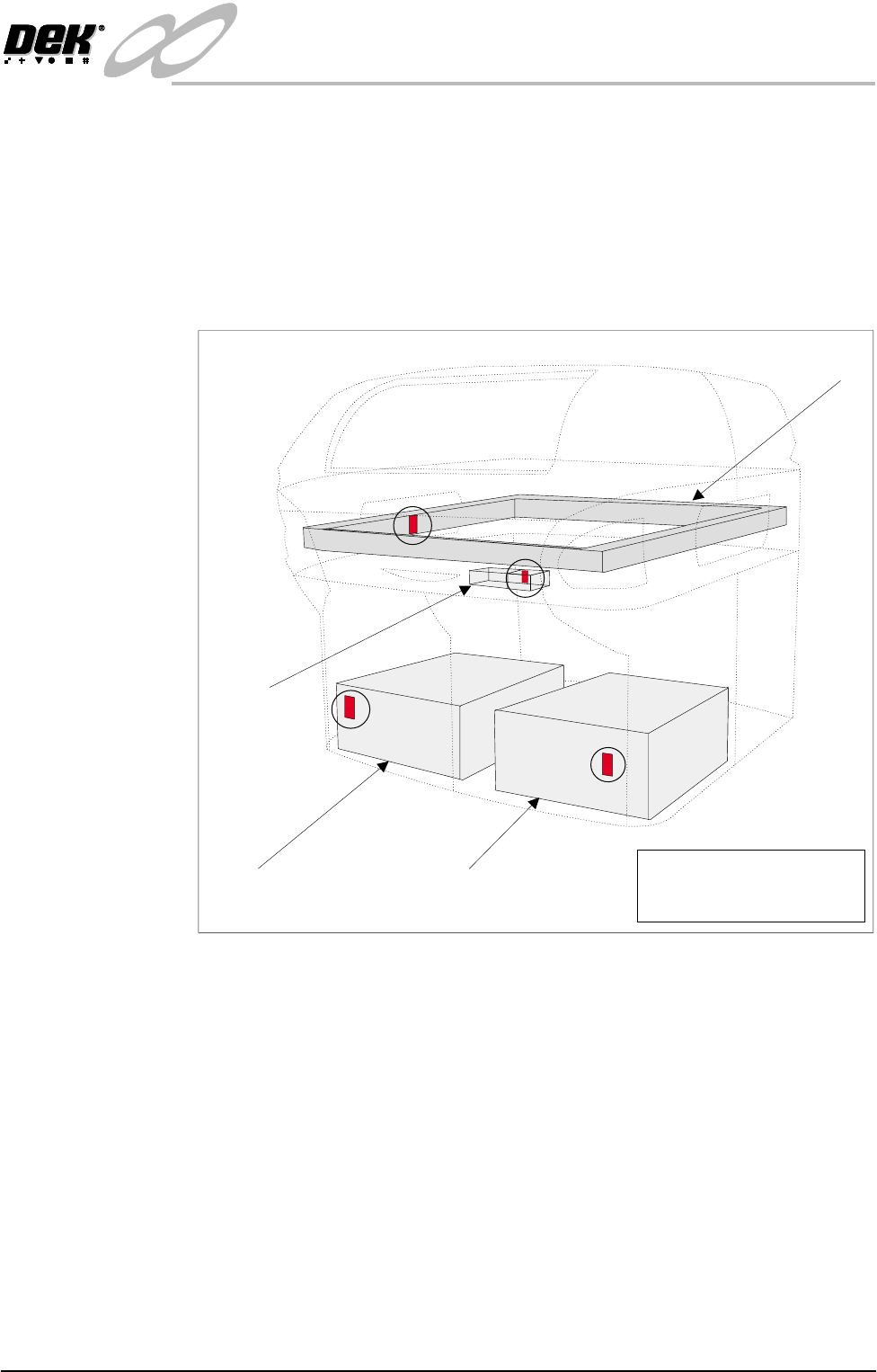
Shock Watches A self adhesive shock watch (DEK Part No. 133517), is fitted in the vertical
plane on the machine in four places (Shock Watch Locations figure refers).
Check if the shock watches have been triggered, the indicator shows red, ('Drop
N Tell' Shockwatch figure refers).
Figure 31-12 Shock Watch Locations
Camera Shock
Watch
If the camera shock watch has triggered, ensure that the camera is secure and
level on the camera mount (refer to the Camera and Vision System Module
Chapter).
Machine PC Shock
Watch
If the machine PC shock watch has triggered, visually inspect the inside of the
PC and ensure that the cards are seated correctly.
Machine Controller
Shock Watch
If the machine controller shock watch has triggered, visually inspect the machine
controller to ensure that the cards are seated correctly.
Chase Shock Watch If the chase shock watch has triggered, visually inspect the chase is level to the
table.
Machine PC Machine Controller
Camera
Chase
NOTE
Shock Watches (4 positions)
shown circled