Infinity EX Transportation.pdf - 第9页
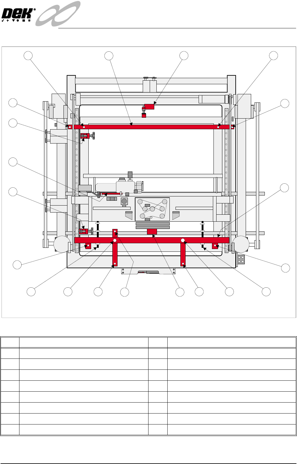
INFINITY EX TRANS PORTATION MAJOR RELO CATION Chapter Issue 3 J an 04 Technical Reference Manual 31.9 Figur e 31-4 T ransit Brackets Machine Location No Description No Description 1 Front T ransit B racket 3 P aste Dispe…

INFINITY
EX
TRANSPORTATION
MAJOR RELOCATION
31.8 Technical Reference Manual Chapter Issue 3 Jan 04
7. Machines fitted with ECU covers - remove the front left hand side ECU plate
(adjacent to the paste dispense unit).
8. Locate and screw the printhead lift studs (Item 1c) into the machine frame
and secure in place using locknuts and washers (2 in number). Secure the
studs to the bracket with nuts and washers (2 in number).
9. Move the chase forward by hand and temporarily hold in position. Ensure
the screen chase is not in contact with the head lift studs. Locate the chase
studs (Item 1a) into the chase, hand tighten only.
10.Remove the squeegee assembly pressure housing cover plate to gain access
to the squeegee timing belts.
Wind the rear squeegee mounting down (front timing belt) so that the mount
comes to rest on the support bracket (Item 1e). Repeat for the front squeegee
mount using the rear timing belt.
11.Locate and screw the print carriage studs (Item 1b) into the threaded holes
of the print carriage front face and secure in place using the nuts and washers.
Secure the studs to the transit bracket with the nuts and washers.
12. Locate the two fixing screws (Item 1d) which secures the front transit bracket
to the printhead casting. Secure the transit bracket to the printhead.
INFINITY
EX
TRANSPORTATION
MAJOR RELOCATION
Chapter Issue 3 Jan 04 Technical Reference Manual 31.9
Figure 31-4 Transit Brackets Machine Location
No Description No Description
1 Front Transit Bracket 3 Paste Dispense Transit Bracket
1a Screen Chase Studs (2 positions) 4 X Rear Chase Restrainer Bracket
1b Print Carriage Studs (2 positions) 5 Rear Transit Bracket
1c Printhead Lift Studs (2 positions) 5a Printhead Casting Fixing Screws (2 positions)
1d Printhead Casting Fixing Screws (2 positions) 5b Screen Chase Studs (2 positions)
1e Squeegee Mount Support Bracket 6 Y Axis Chase Restrainer Bracket
1f Camera Carriage Fixing Screw 7 Printhead Safety Prop
2 X Front Chase Restrainer Bracket
1
1a
1b
1c
1a
1b 1c
2
3
5a
5b
6
4
5a
5b
5
Plan View of Machine
1d
1d
1f
1e
INFINITY
EX
TRANSPORTATION
MAJOR RELOCATION
31.10 Technical Reference Manual Chapter Issue 3 Jan 04
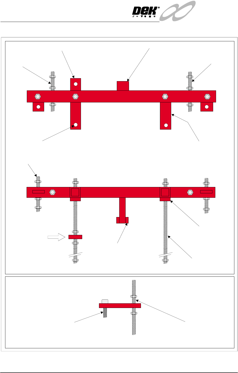
Figure 31-5 Front Transit Bracket and Camera Transit Bracket
Plan View on Front Transit Bracket
Printhead Carriage
Stud
Camera Carriage Transit Bracket Squeegee Mounting Bracket
Transit Bracket
Mounting Feet (2 positions)
Printhead Carriage
Stud
Transit Bracket
Fixing Screws (2 positions)
Front View on Front Transit Bracket
Side View on Camera Carriage Transit Bracket
(View on Arrow A)
A
Camera Carriage Securing Screw LH Printhead Lift Stud
Printhead Lift Stud
(2 positions)
Squeegee Mounts
Support Bracket
Transit Bracket
Mounting Feet
(2 positions)
Screen Chase Studs, Front (2 positions)