Infinity EX Transportation.pdf - 第5页
INFINITY EX TRANS PORTATION MINOR RELO CATION Chapter Issue 3 J an 04 Technical Reference Manual 31.5 T ransportation W ARNING MA CHINE LIFTING. TO PREVENT SERIOUS INJUR Y TO PERSONNEL, DURING LIFTING AND TRANSPOR T A TI…
INFINITY
EX
TRANSPORTATION
MINOR RELOCATION
31.4 Technical Reference Manual Chapter Issue 3 Jan 04
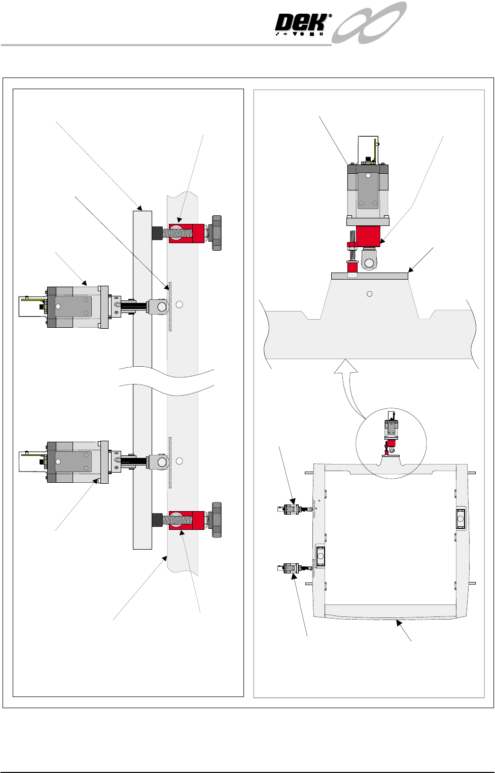
Figure 31-2 X and Y Axis Chase Restrainer Positions
Chase Casting
X Rear Actuator
X Forward Actuator
Printhead Casting X Axis Rear Chase
Restrainer Bracket
X Axis Front Chase
Restrainer Bracket
X Axis Chase Restrainer Positions
(Actuator springs removed for clarity)
X Rear Actuator
X Front Actuator Chase Casting
Y Axis Chase Restrainer Position
(Actuator spring removed for clarity)
Y Axis Chase
Restrainer Bracket
Striker Plate
(2 positions)
Y Actuator
Chase Striker
Plate
INFINITY
EX
TRANSPORTATION
MINOR RELOCATION
Chapter Issue 3 Jan 04 Technical Reference Manual 31.5
Transportation
WARNING
MACHINE LIFTING. TO PREVENT SERIOUS INJURY TO
PERSONNEL, DURING LIFTING AND TRANSPORTATION
OPERATIONS, ENSURE THE MACHINE IS LIFTED AND
TRANSPORTED IN ACCORDANCE WITH INSTRUCTIONS
DETAILED IN THIS SECTION.
CAUTION
MACHINE DAMAGE. Damage to the machine will occur if the machine
is lifted:
• Using lifting strops
• From the sides
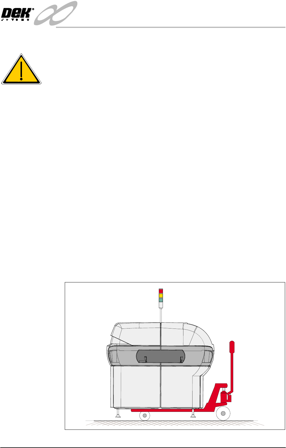
The machine may be lifted using a pallet trolley or similar manually operated
machine that meets the following criteria:
• Has two 48 inch long forks
• The forks have a 27 inch span
• Has a lifting capability of 2000kg
1. Locate the forks under the machine base so the weight of the machine is
taken evenly on the front and rear cross members.
NOTE
Height of machine feet may have to be adjusted to allow the pallet trolley to
raise the machine clear of the floor.
2. Raise the machine and carefully transport into position.
Figure 31-3 Machine on Pallet Truck

INFINITY
EX
TRANSPORTATION
MINOR RELOCATION
31.6 Technical Reference Manual Chapter Issue 3 Jan 04
Transit Bracket
Removal
CAUTION
SCREEN ACTUATOR BRACKETS. Extreme care must be taken when
installing or removing the screen actuator brackets as the chase is spring
loaded against the screen actuator ends in the X Forward, X Rear and Y
Axis Positions. Impact force may damage the actuators.
1. On the two X axis chase restrainer brackets (X and Y Chase Restrainer
Brackets figure refers), release the locknuts by turning them in an anti-
clockwise direction. Slowly turn the black hand wheels in an anti-clockwise
direction until the actuators have made contact with the chase striker plates.
Continue to turn the hand wheels until the threads have withdrawn enough
to allow access to the lower cap head screws.
2. On the Y axis chase restrainer bracket (X and Y Chase Restrainer Brackets
figure refers), release the locknut. Slowly undo the cap head screw until the
actuator has made contact with the chase striker plate. Continue to undo the
cap head screw until the bracket can be easily removed from the Y axis
actuator.
On completion of relocation, carry out the following:
1. Reconnect electrical power supplies.
2. Reconnect pneumatic supplies.