Infinity EX Transportation.pdf - 第4页
INFINITY EX TRANSPORT ATION MINOR RELO CATION 31.4 Technical Reference Manu al Chapter Is sue 3 Jan 04 Figure 31-2 X and Y Axis Chase Restrainer Positions Chase Casting X Rear Actuator X F orwar d Actuator P rinthead Cas…
INFINITY
EX
TRANSPORTATION
MINOR RELOCATION
Chapter Issue 3 Jan 04 Technical Reference Manual 31.3
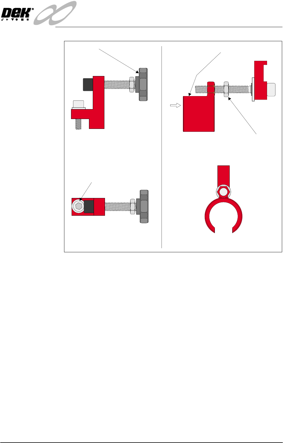
Figure 31-1 X and Y Axis Chase Restrainer Brackets
Y Axis Chase
Restrainer Bracket
1. Position the 'C' shaped bracket of the Y axis chase restrainer bracket over the
end of the Y axis chase actuator.
2. Position the smaller end of the restrainer bracket so that its recess fits snugly
onto the chase striker plate.
3. Using an Allen key, extend the restrainer slowly until the striker plate no
longer makes contact with the actuator (approx. 6mm distance).
4. Tighten the restrainer bracket locknut up to the 'C' shaped bracket.
5. Visually check that the actuator clears the striker plate.
Side View on X Axis Restrainer
Plan View on X Axis Restrainer
Cap Headed Bolt
Hand Wheel
Side View on Y Axis Restrainer
View on Arrow A
Locknut
'C' Shaped Restrainer Bracket
A
INFINITY
EX
TRANSPORTATION
MINOR RELOCATION
31.4 Technical Reference Manual Chapter Issue 3 Jan 04
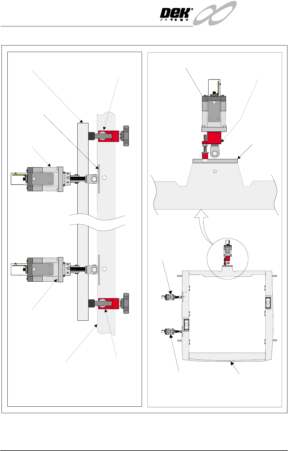
Figure 31-2 X and Y Axis Chase Restrainer Positions
Chase Casting
X Rear Actuator
X Forward Actuator
Printhead Casting X Axis Rear Chase
Restrainer Bracket
X Axis Front Chase
Restrainer Bracket
X Axis Chase Restrainer Positions
(Actuator springs removed for clarity)
X Rear Actuator
X Front Actuator Chase Casting
Y Axis Chase Restrainer Position
(Actuator spring removed for clarity)
Y Axis Chase
Restrainer Bracket
Striker Plate
(2 positions)
Y Actuator
Chase Striker
Plate
INFINITY
EX
TRANSPORTATION
MINOR RELOCATION
Chapter Issue 3 Jan 04 Technical Reference Manual 31.5
Transportation
WARNING
MACHINE LIFTING. TO PREVENT SERIOUS INJURY TO
PERSONNEL, DURING LIFTING AND TRANSPORTATION
OPERATIONS, ENSURE THE MACHINE IS LIFTED AND
TRANSPORTED IN ACCORDANCE WITH INSTRUCTIONS
DETAILED IN THIS SECTION.
CAUTION
MACHINE DAMAGE. Damage to the machine will occur if the machine
is lifted:
• Using lifting strops
• From the sides
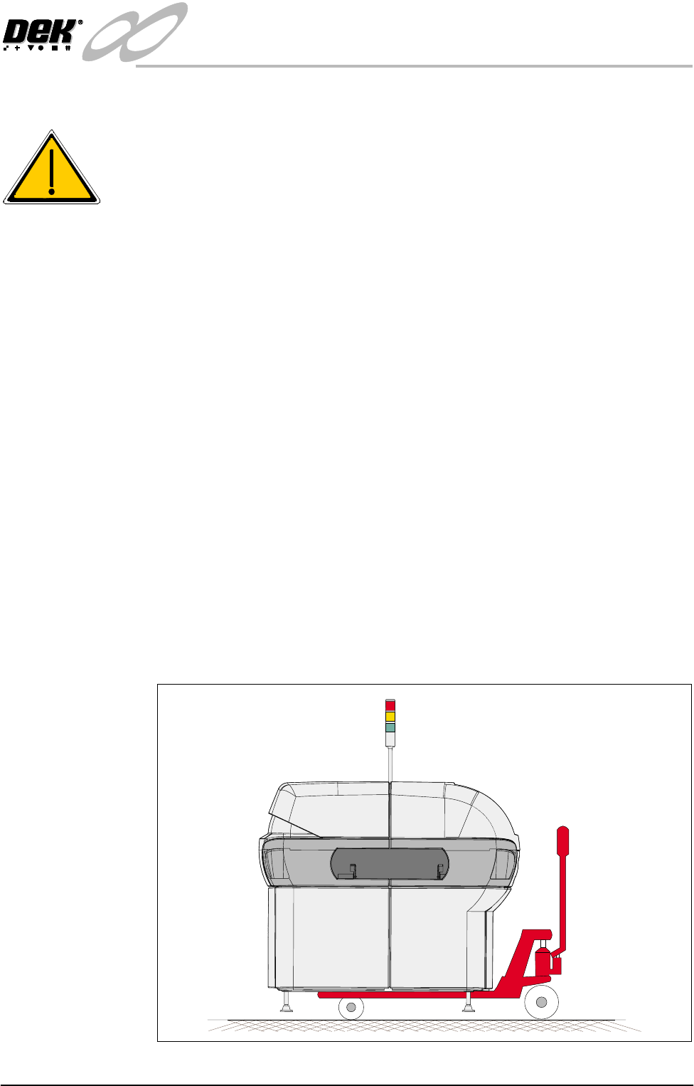
The machine may be lifted using a pallet trolley or similar manually operated
machine that meets the following criteria:
• Has two 48 inch long forks
• The forks have a 27 inch span
• Has a lifting capability of 2000kg
1. Locate the forks under the machine base so the weight of the machine is
taken evenly on the front and rear cross members.
NOTE
Height of machine feet may have to be adjusted to allow the pallet trolley to
raise the machine clear of the floor.
2. Raise the machine and carefully transport into position.
Figure 31-3 Machine on Pallet Truck