Infinity EX Transportation.pdf - 第3页
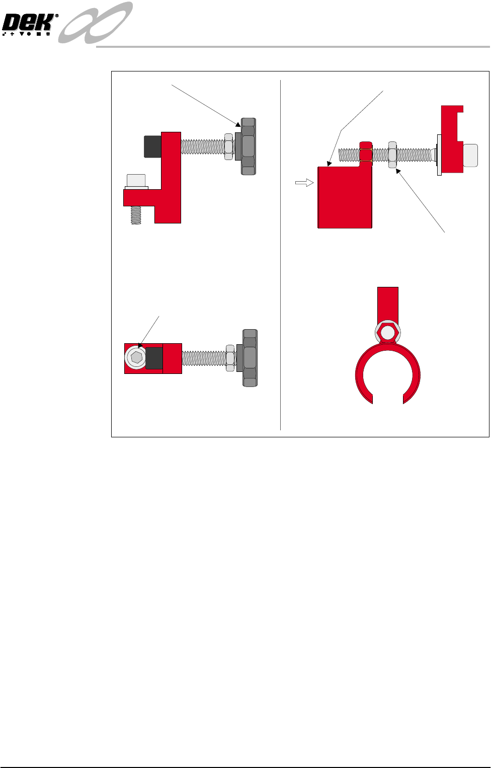
INFINITY EX TRANS PORTATION MINOR RELO CATION Chapter Issue 3 J an 04 Technical Reference Manual 31.3 Figure 31-1 X and Y Axis Chase Restrainer Brackets Y Axis Chase Restr ainer Br acket 1. Po sition th e 'C ' …

INFINITY
EX
TRANSPORTATION
MINOR RELOCATION
31.2 Technical Reference Manual Chapter Issue 3 Jan 04
MINOR RELOCATION
This procedure is given when the machine is being relocated on the following
occasions:
• The machine is brought out of line for servicing and or fault rectification.
• The machine is being relocated a short distance from it’s original position,
ie within the confines of the factory utilizing a pallet trolley or similar
manually operated machine.
CAUTION
SCREEN ACTUATOR BRACKETS. Extreme care must be taken when
installing or removing the screen actuator brackets as the chase is spring
loaded against the screen actuator ends in the X Forward, X Rear and Y
Axis Positions. Impact force may damage the actuators.
Transit Bracket
Installation
Prior to installing transit brackets to the machine ensure the following machine
conditions are met:
1. With power applied to the machine home the X and Y screen actuators.
2. Switch off and disconnect the electrical power.
3. Disconnect the pneumatic supply.
X Axis Chase
Restrainer Brackets
NOTE
For guidance, when fitting the restrainer brackets, refer to the following figures:
• X and Y Axis Chase Restrainer Brackets
• X and Y Axis Chase Restrainer Positions
1. Wind the hand wheels on both of the X axis chase restrainer brackets in an
anti-clockwise direction until the lower cap head screws are accessible.
2. Position the two X axis chase restrainer brackets on the chase.
3. Screw the 6mm cap head bolts until the brackets are fixed firmly in place.
4. Turn the knobs on each bracket clockwise by hand until the X axis actuators
are no longer in contact with the chase (approx. 6mm gap).
5. Tighten the locknuts.
INFINITY
EX
TRANSPORTATION
MINOR RELOCATION
Chapter Issue 3 Jan 04 Technical Reference Manual 31.3
Figure 31-1 X and Y Axis Chase Restrainer Brackets
Y Axis Chase
Restrainer Bracket
1. Position the 'C' shaped bracket of the Y axis chase restrainer bracket over the
end of the Y axis chase actuator.
2. Position the smaller end of the restrainer bracket so that its recess fits snugly
onto the chase striker plate.
3. Using an Allen key, extend the restrainer slowly until the striker plate no
longer makes contact with the actuator (approx. 6mm distance).
4. Tighten the restrainer bracket locknut up to the 'C' shaped bracket.
5. Visually check that the actuator clears the striker plate.
Side View on X Axis Restrainer
Plan View on X Axis Restrainer
Cap Headed Bolt
Hand Wheel
Side View on Y Axis Restrainer
View on Arrow A
Locknut
'C' Shaped Restrainer Bracket
A
INFINITY
EX
TRANSPORTATION
MINOR RELOCATION
31.4 Technical Reference Manual Chapter Issue 3 Jan 04
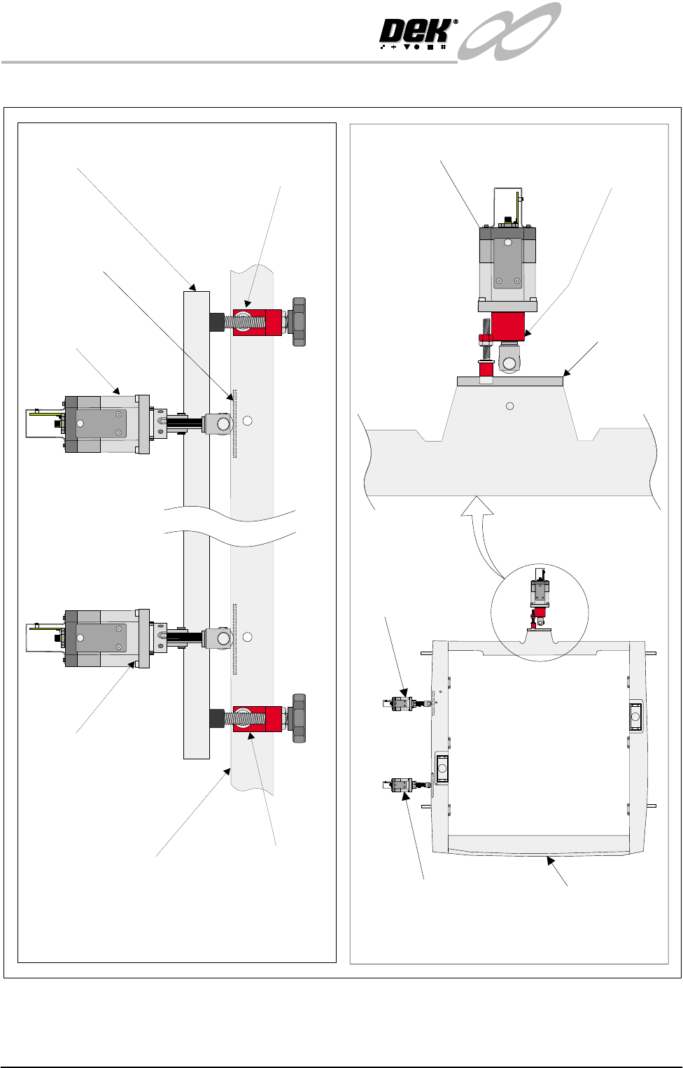
Figure 31-2 X and Y Axis Chase Restrainer Positions
Chase Casting
X Rear Actuator
X Forward Actuator
Printhead Casting X Axis Rear Chase
Restrainer Bracket
X Axis Front Chase
Restrainer Bracket
X Axis Chase Restrainer Positions
(Actuator springs removed for clarity)
X Rear Actuator
X Front Actuator Chase Casting
Y Axis Chase Restrainer Position
(Actuator spring removed for clarity)
Y Axis Chase
Restrainer Bracket
Striker Plate
(2 positions)
Y Actuator
Chase Striker
Plate