Infinity EX Transportation.pdf - 第41页
INFINITY EX TRANS PORTATION MAJOR RELO CATION Chapter Issue 3 J an 04 Technical Reference Manual 31.41 a. Adjust the right hand auxilia ry con veyor rail width to app roximately 250mm . b . Place a Board Clamp Setting Pl…
INFINITY
EX
TRANSPORTATION
MAJOR RELOCATION
31.40 Technical Reference Manual Chapter Issue 3 Jan 04
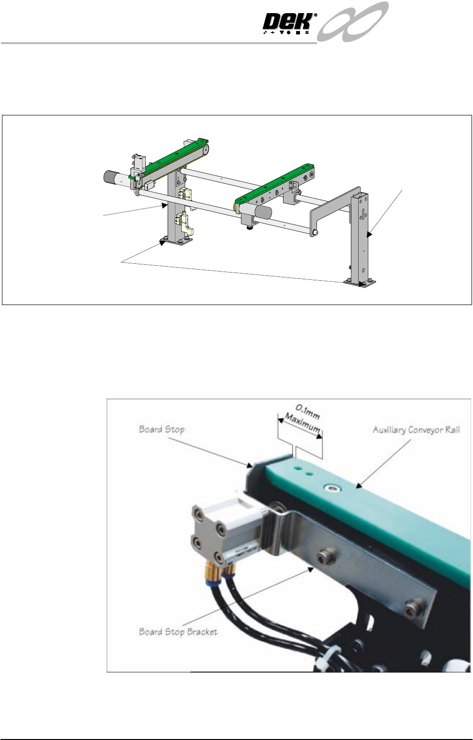
d. If adjustment is required, carefully adjust the position of the conveyor to
obtain the 3.0±0.5mm gap.
e. Tighten the M5 securing bolts fitted in Step 11.
f. Refit the board stop and bracket to the auxiliary conveyor using the two
M5 caphead screws removed in Step 3b. DO NOT fully tighten the
screws.
g. Using a feeler gauges check the gap between the auxiliary conveyor rail
and the inner face of board stop is a maximum of 0.1mm . Adjust the gap
as necessary by repositioning the board stop bracket.
h. Tighten the screws fitted 3f and recheck the gap.
13.Carry out the following procedure to check and if required adjust the right
hand auxiliary conveyor levelling:
Rear View of Right Auxiliary Conveyor
Front Auxiliary Conveyor
Rail Support
Rear Auxiliary Conveyor
Rail Support
Rail Support to Main Frame
Bolts (4 bolts in 2 positions)
INFINITY
EX
TRANSPORTATION
MAJOR RELOCATION
Chapter Issue 3 Jan 04 Technical Reference Manual 31.41
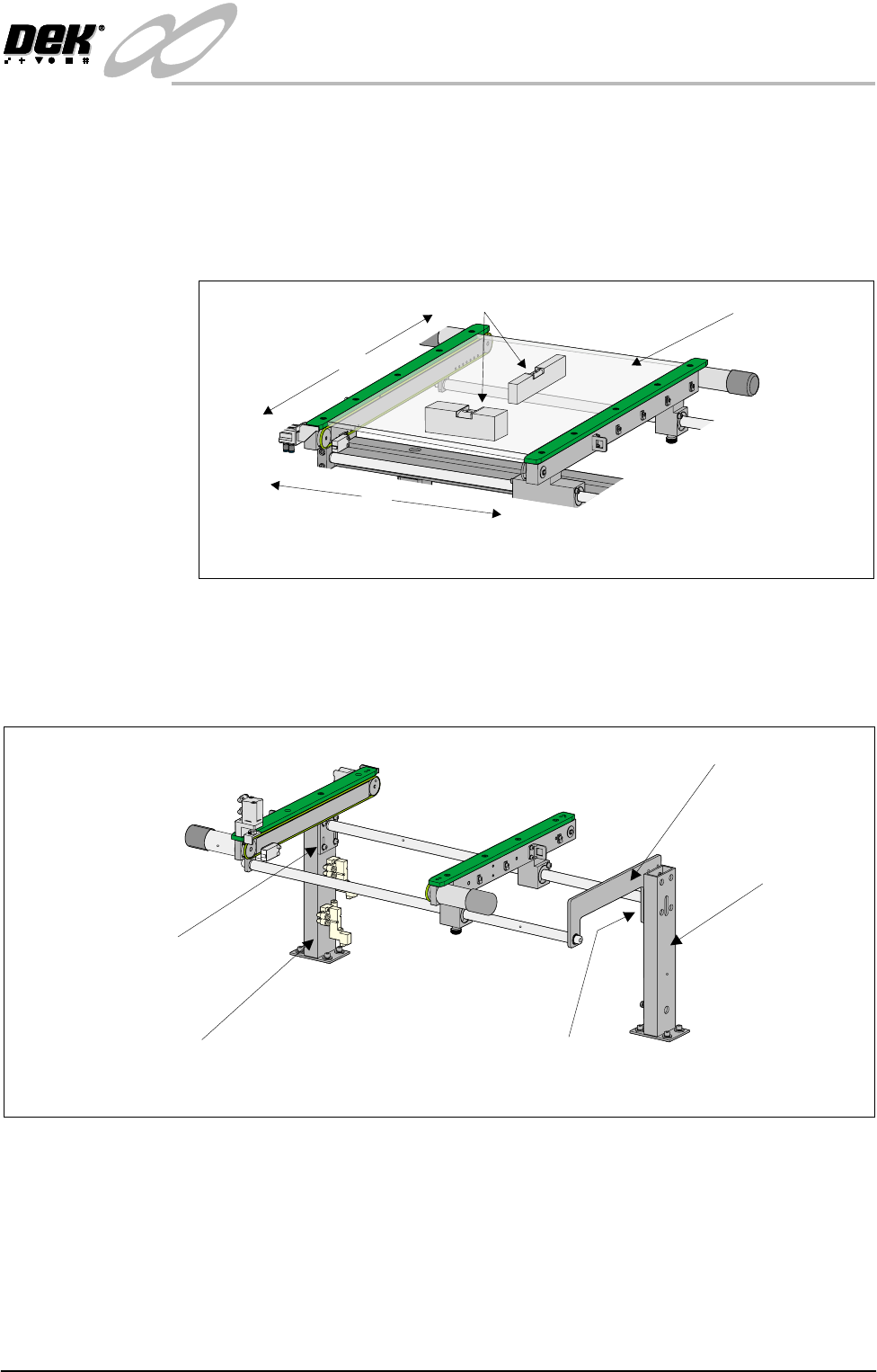
a. Adjust the right hand auxiliary conveyor rail width to approximately
250mm.
b. Place a Board Clamp Setting Plate Pt No 140403 onto the auxiliary
conveyor transport belts.
c. Place a spirit level on top of the setting plate and check the levelness of
the conveyor in the X and Y planes.
d. If adjustment is required, carry out Steps 13e - 13g.
e. Loosen the four bolts that secure the auxiliary conveyor shaft guide plate
to the rear rail support and the four bolts that secure the rail bracket to front
rail support.
f. Carefully adjust the height of the auxiliary conveyor rails to achieve
conveyor levelness in the X and Y planes.
g. Re-tighten the rail bracket and shaft guide plate securing bolts and repeat
the check.
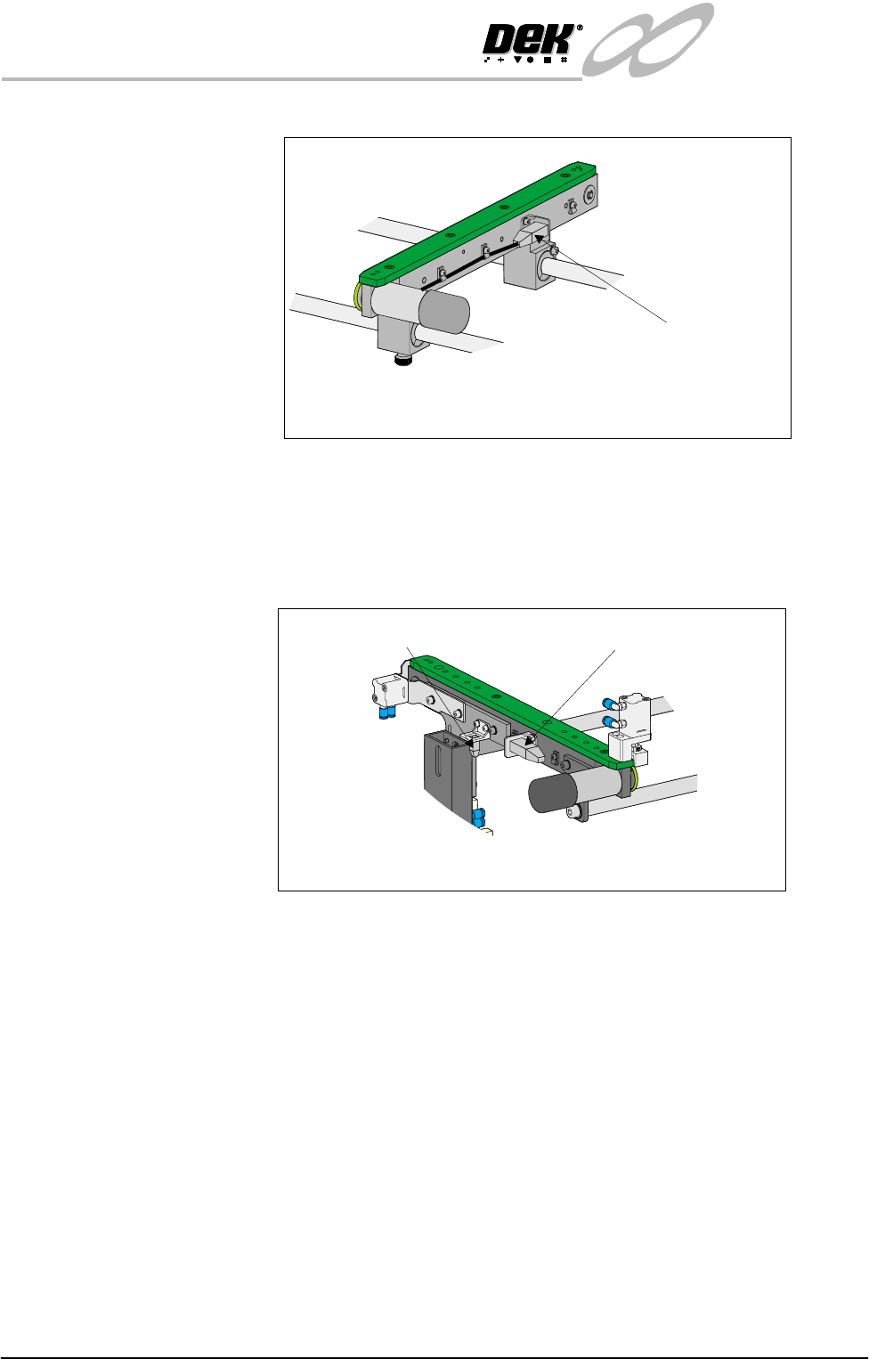
14.Connect M27PL17 connector to the rear transport belt motor fitted to the rear
X
Y
Board Clamp
Setting Plate
View on Auxiliary Conveyor
Spirit Level
Rear View of Right Auxiliary Conveyor
Front Auxiliary Conveyor
Rail Support
Rear Auxiliary Conveyor
Rail Support
Shaft Guide Plate
Shaft Guide Plate to Rear
Rail Support Bolts (4 off)
Rail Bracket to Front
Rail Support Bolts
(in 4 positions)
INFINITY
EX
TRANSPORTATION
MAJOR RELOCATION
31.42 Technical Reference Manual Chapter Issue 3 Jan 04
face of the auxiliary conveyor rail.
15.Connect to the following connectors situated on the front auxiliary conveyor
rail:
• M27SK14 - Auxiliary conveyor sensor
• M27PL16 - Auxiliary conveyor front transport belt motor
16.Connect the electrical supply connectors to the pneumatic solenoid valves
M27SOL01 and M27SOL03 situated on the rear face of the front rail
support.
17.Connect solenoid valves M27SOL01and M27SOL03 with the 4mm pneum-
tic pipe at the tee piece connection to valve M27SOL03.
18.Refit the right hand machine side covers removed in Step10.
19.The following auxiliary conveyor checks are to be carried out:
• Auxiliary Conveyor Rail Parallelism
• Auxiliary Conveyor Height Setting
These checks require power to be available to the machine and are detailed
later in this chapter.
Fitting of Machine
Safety Covers (HTC
Option)
To fit the machine safety covers carry out the following:
1. Attach a safety plate to the top of each pair of auxiliary conveyor rails using
Connector M27PL17
Rear View on Right Auxiliary Conveyor
Front View on Right Hand Auxiliary Conveyor
Connector M27SK14
Connector M27PL16