Infinity EX Transportation.pdf - 第47页
INFINITY EX TRANS PORTATION PRE IN STALLAT ION CH ECKS Chapter Issue 3 J an 04 Technical Reference Manual 31.47 Machin e Le vel ling The machine must be installed at the cor rect height and lev e lled before opera- tion.…
INFINITY
EX
TRANSPORTATION
PRE INSTALLATION CHECKS
31.46 Technical Reference Manual Chapter Issue 3 Jan 04
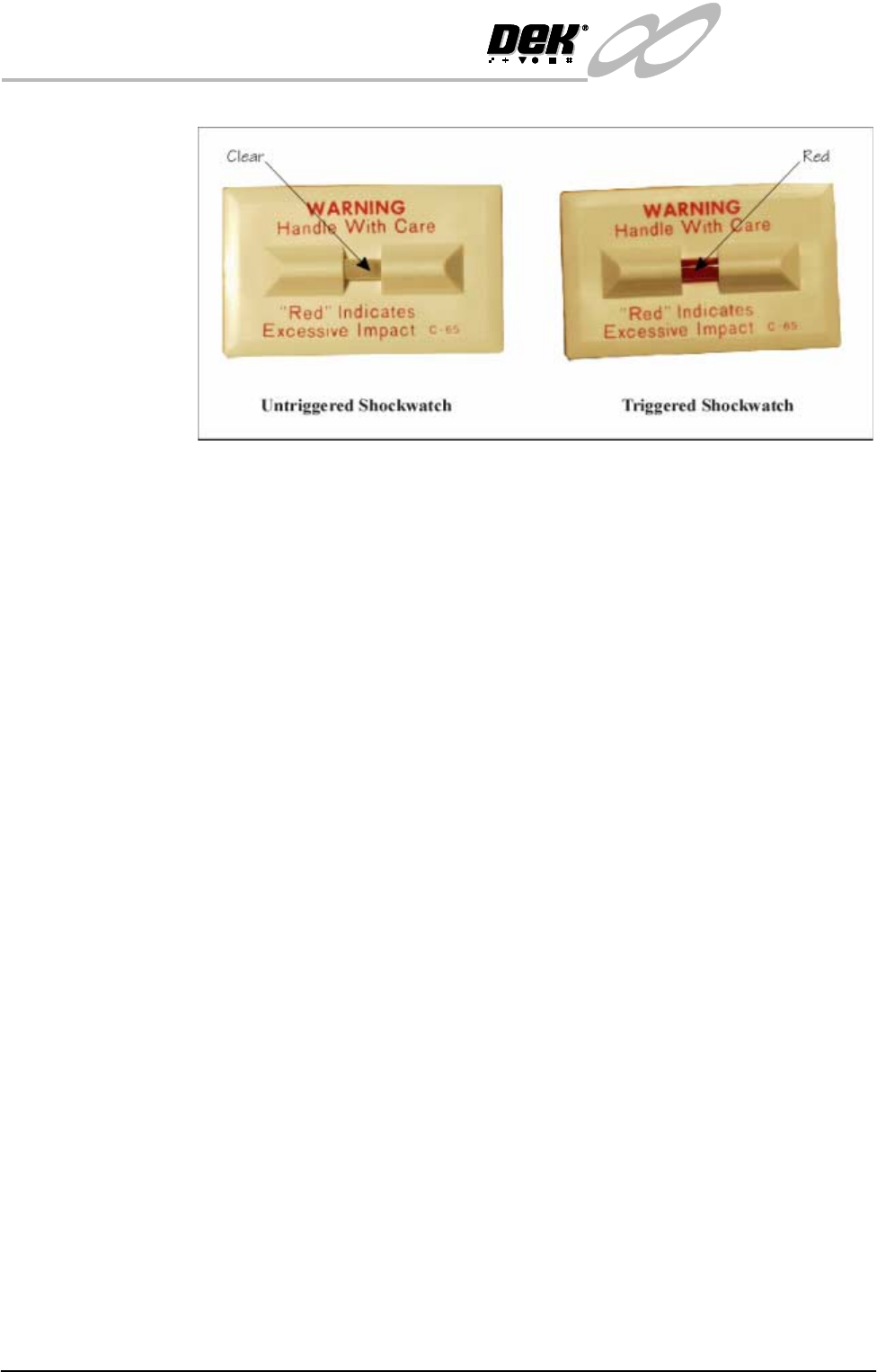
Figure 31-13 Drop N Tell Shockwatch
Shock Watch
Replacement
On completion of corrective action, replace any triggered shock watches.
NOTE
The machine should be fitted with four untriggered shock watches at all times.
Preparations 1. Ensure machine mains isolator is OFF.
2. Connect the pneumatic supply to the connection on the external services
panel.
NOTE
Do not connect electrical supply to the machine until the electrical services
available have been verified.
3. Ensure the machine transformer is tapped to the nearest selectable voltage
within the following limits:
• 100V, 110V, and 120V ±5%
• 200V, 210V, 220V, 230V and 240V ±2.5%
NOTE
In the event that local electrical services necessitate reconfiguration, refer
to Power Supply and Distribution chapter.
The machine is able to handle ±10V variations without overloading, but
some degradation in speed may be experienced if the supply remains at -10V
or more from the tapped voltage.
4. Check that the E Stop loop is connected, either to the external machines, in
which case these machines must be powered up and operational in order for
the loop to be closed, or if the external E Stop loop is not required the dummy
plugs supplied with the machine must be connected.
5. Check that all circuit breakers are in the ON position.
6. Ensure that all access covers and removable panels are closed and are in
place.
7. Ensure that the E Stop button is in the fully out position. To check this, push
the E Stop button until it latches. Twist the button clockwise to release it.
8. Check that all of the cables for the monitor are connected.
INFINITY
EX
TRANSPORTATION
PRE INSTALLATION CHECKS
Chapter Issue 3 Jan 04 Technical Reference Manual 31.47
Machine Levelling The machine must be installed at the correct height and levelled before opera-
tion.
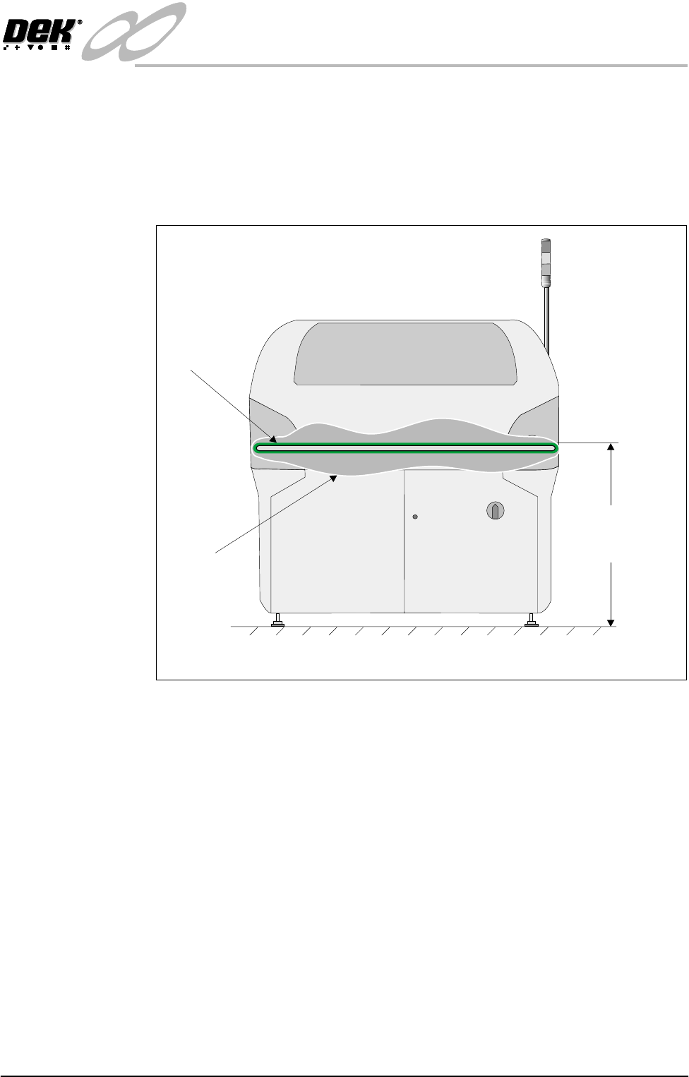
Machine Height The height of the machine is governed by the external machines that it is to be
connected to and ranges from 840mm to 980mm (depending if the feet exten-
sions are fitted). The height is measured from the floor to the top of the transport
belts. Adjust the four feet to achieve the desired height.
Figure 31-14 Machine Height
Initial Levelling When the correct height of the machine has been achieved, the four feet should
now be adjusted for correct level.
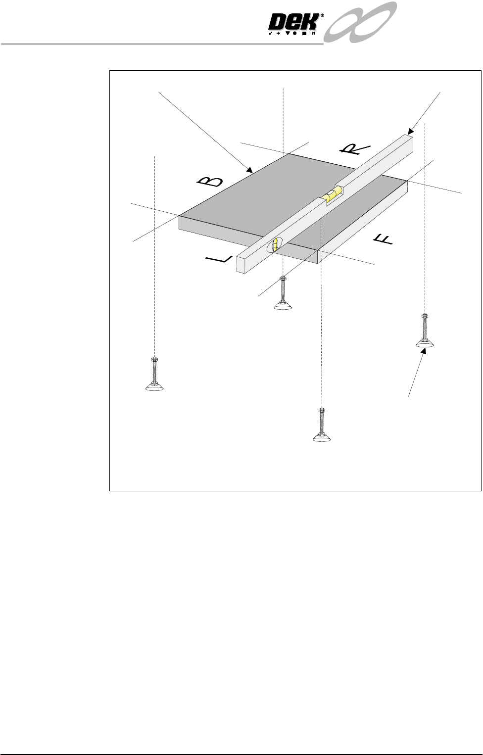
Place an Engineering level on the tooling base plate facing Left (L) - Right (R)
or Back (B) - Front (F).
By carefully adjusting each of the four feet individually, level the machine so
that in each direction, Left (L) - Right (R) and Back (B) - Front (F), 0.004” per
foot (0.32mm/metre) is achieved. Lock the feet using the lock-nuts on the
adjusters.
Check that the height has not been disturbed. Repeat until the correct height and
level are achieved.
Transport
Belt
Cutaway
Section
Height to Topof
TransportBelts
840 mm to 980 mm
View on Front of Machine
INFINITY
EX
TRANSPORTATION
PRE INSTALLATION CHECKS
31.48 Technical Reference Manual Chapter Issue 3 Jan 04
Figure 31-15 Machine Levelling
Isometric View Showing Levelling of Tooling Base Plate
Tooling Base Plate Engineering Level
Adjustable Mounting Feet
(4 positions)