instruction-manual-product-monitoring-data-acquisition-monitouch-V9-hardware-en.pdf - 第102页
1. Installation Procedure 4-1 4 Installation 1. Installation Procedure Installation Procedure 1. Place the V9 series unit on a flat surface with the display facing down. Insert the provided waterproof gasket into the gr …

1. Installation Procedure 4-1
4
Installation
1. Installation Procedure
Installation Procedure
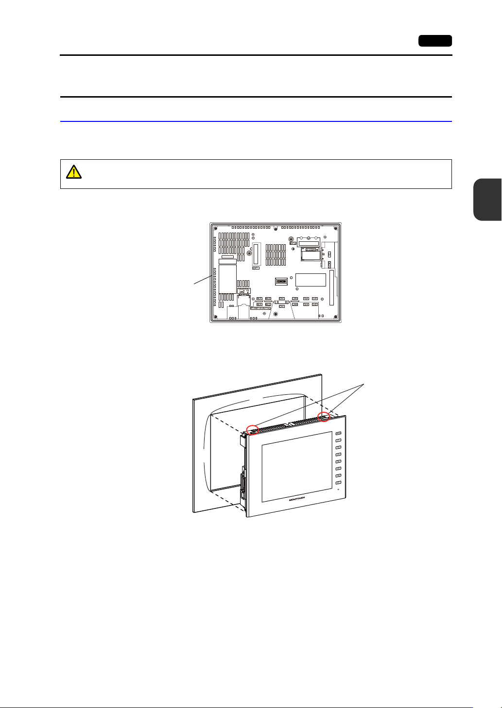
1. Place the V9 series unit on a flat surface with the display facing down.
Insert the provided waterproof gasket into the groove around the unit.
2. Mount the V9 series unit into the mounting panel (maximum thickness of 4.0 mm) while paying
attention to the fall prevention tabs.
CAUTION
The unit will not be waterproof if the waterproof gasket is not correctly inserted into
the groove.
Waterproof gasket
Example: When mounting the V9100iS unit in the upright orientation
X
Y
Fall prevention tabs
4-2 1. Installation Procedure
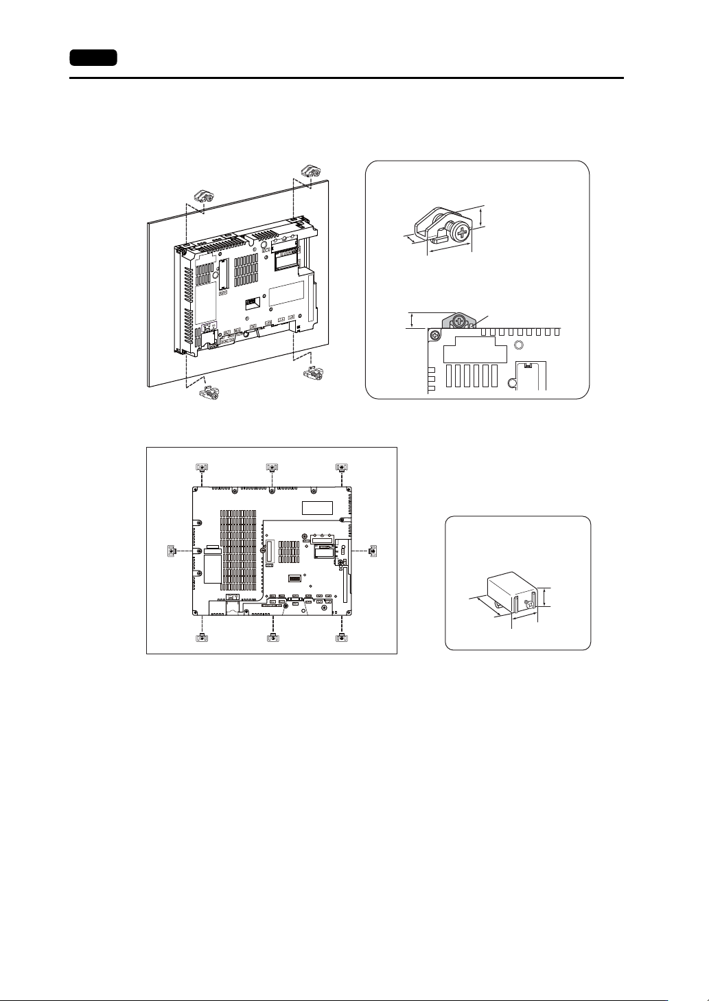
3. Insert the four fixtures provided with the V9 series unit into the mounting holes and tighten them
with the tightening screws (tightening torque: 5.31 Ibf-in (0.6 N·m)).
For the V9150 series, use eight fixtures to mount the unit.
* If the screws are tightened to a torque higher than stated above or the torque at each location
is not equal, the surface sheet may warp due to deformation in the mounting panel and unit.
* When mounting the V9 series unit rotated 90 to the right or left, insert and secure the fixtures
in the same mounting holes shown in the figure below.
* Ground the mounting panel to prevent any buildup of static electricity.
22.0
9.6
9.0
9.6
Fixture dimensions (unit: mm)
Dimensions of a tightened fixture that
protrudes from the edge of the V9 series
unit (unit: mm)
Fall prevention tab
17.8
10.5
30.0
Fixture dimensions
(unit: mm)