instruction-manual-product-monitoring-data-acquisition-monitouch-V9-hardware-en.pdf - 第69页
3-4 1. Names and Functions of Components 9. Fall prevention tabs These tabs prevent the V9 series unit from fallin g off the mounting panel until the mounting fixtures are tightened. 10. DIP switches This 8-bit DIP switc…
3
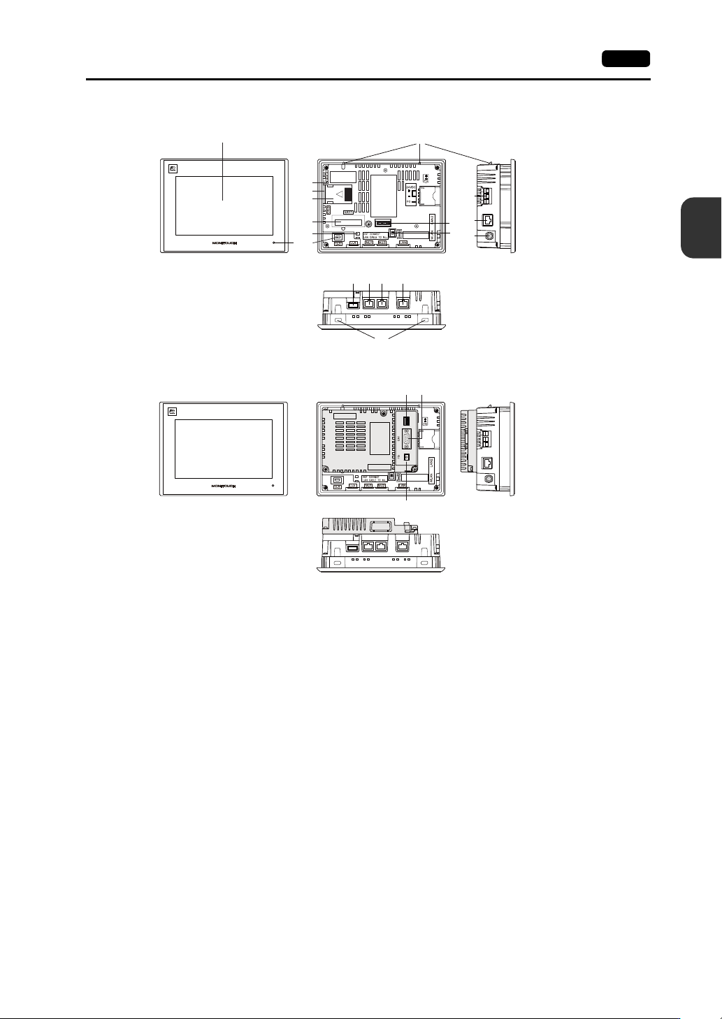
1. Names and Functions of Components 3-3
Names and Specifications of Components
1. Display
This is the display area.
2. POWER lamp
This lamp illuminates green when the V9 series is powered ON and operating normally.
The lamp flashes when there is a failure (circuit board failure, power supply failure).
3. SD card access LED
This LED flashes when the unit is reading from or writing to an SD card.
4. SD card slot (SD)
This slot is where an SD card can be inserted.
5. Battery holder
This part contains the backup battery for the SRAM and clock.
When the battery voltage drops, replace the battery with a new one.
6. Communication interface unit connector (EXT1)
This connector is used to connect the optional “DUR-00” unit or any “CUR-xx” communication
interface unit (for SX-BUS, OPCN-1, T-Link, CC-Link, Ethernet, PROFIBUS-DP, DeviceNet, and
FL-net).
* The “DUR-00” and “CUR-xx” cannot be used at the same time.
7. USB cable clamp hole
This clamp hole is used to attach a USB cable tie.
8. USB mini-B (U-B)
This port is used for transferring screen programs or connecting a PictBridge-compatible printer.
1
2
11
19
10
15 16 17 18
12
13
14
3
4
5
6
7
9
8
20 21
22
V907xiW
V907xiW+DUR-00

3-4 1. Names and Functions of Components
9. Fall prevention tabs
These tabs prevent the V9 series unit from falling off the mounting panel until the mounting fixtures
are tightened.
10. DIP switches
This 8-bit DIP switch is used for setting the terminating resistance of the MJ1/MJ2 RS-485 signal
line.
11. Sliding switch
This switch is for selecting the RS-232C/RS-485 signal (2-wire connection) or the RS-422 signal
(4-wire connection) for MJ2. The upper side is for the RS-232C/RS-485 signal (2-wire connection)
and the lower side is for the RS-422 signal (4-wire connection).
12. Power supply terminal block
This terminal block is for supplying power (24 VDC) to the V9 series unit.
13. 100BASE-TX/10BASE-T connector (LAN2)
This connector is used for Ethernet communication.
14. Connector for wireless LAN dipole antenna (WLAN)
Only for wireless LAN I/F models.
This connector is for connecting the external dipole antenna “V9-ANT” (optional) for wireless LAN.
15. USB-A (U-A)
This port is used to connect a printer, USB flash drive, keyboard, or mouse.
16. Modular jack 1 (MJ1)
This connector is used for screen program transfer and connection with PLCs or other peripheral
devices.
17. Modular jack 2 (MJ2)
This connector is used for connection with PLCs or other peripheral devices.
18. 100BASE-TX/10BASE-T connector (LAN)
This connector is used for Ethernet communication.
19. Mounting holes
The mounting holes are used for inserting fixtures when securing the V9 series unit to a mounting
panel.
20. DIP switches (optional “DUR-00” unit)
These switches are used for setting the terminating resistance of the CN1 signal line.
21. PLC communication connector (CN1) (optional “DUR-00” unit)
This connector is used for connection to a controller (PLC, temperature controller, inverter, etc.).
22. FG terminal (FG) (optional “DUR-00” unit)
This is used for connecting FG wire of the communication cable.