instruction-manual-product-monitoring-data-acquisition-monitouch-V9-hardware-en.pdf - 第86页
3 2. Specifications of Components 3-21 Names and Specifications of Components Additional LAN Connector (LAN2) (Only for Additional Wi red LAN I/F Models) This connector is used for Ethernet communicati on with controller…
3-20 2. Specifications of Components
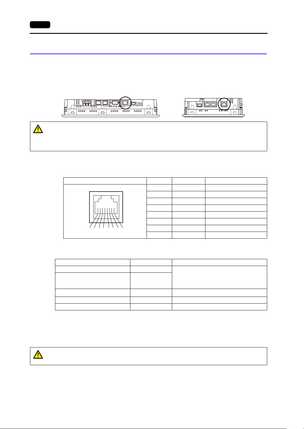
LAN Connector (LAN)
This connector is used for Ethernet communication with controllers and supports 100BASE-TX and
10BASE-T.
The LAN connector pins correspond to the signals as shown below.
Specification: IEEE802.3 (u)-compliant, UDP/IP and TCP/IP support, Auto-MDIX and
Auto-Negotiation function support
Applications
*1 The ladder transfer function cannot be used simultaneously with 1:n communication (multi-drop) or multi-link
communication.
Wiring
Use a commercially available cable. Using a custom-made cable may prevent normal connection to
the network.
Recommended cable: 100 UTP (unshielded twist-pair) cable, category 5, max. 100 m long
* Both straight and cross cables are usable, irrespective of the presence or absence of a hub.
Bottom view Bottom view
V9100 V907xiW
CAUTION
The MJ1 (or MJ2) and LAN connectors are both 8-pin modular jacks.
Check the connector names on the unit and insert cables into the correct connectors.
Do not connect any peripheral device that will carry excess voltage to the LAN
connector.
LAN Pin No. Signal Description
1 TX+ Ethernet send signal (+)
2TX Ethernet send signal ()
3 RX+ Ethernet receive signal (+)
4 NC Not used
5 NC Not used
6RX Ethernet receive signal ()
7 NC Not used
8 NC Not used
8 76 5 43 21
Application V-SFT-6 Setting Refer to
PLC/temperature controller connection Required
V9 Series Connection Manual
Multi-link2 (Ethernet)/
1:n Multi-link2 (Ethernet)
communication
Required
Ladder transfer function
*1
Required V9 Series Reference Manual 2
Screen program transfer Required V9 Series Setup Manual
Ethernet communication function Required V9 Series Reference Manual 2
CAUTION
When using the LAN port, keep the LAN cable away from the power supply cable as
much as possible.
3
2. Specifications of Components 3-21
Names and Specifications of Components
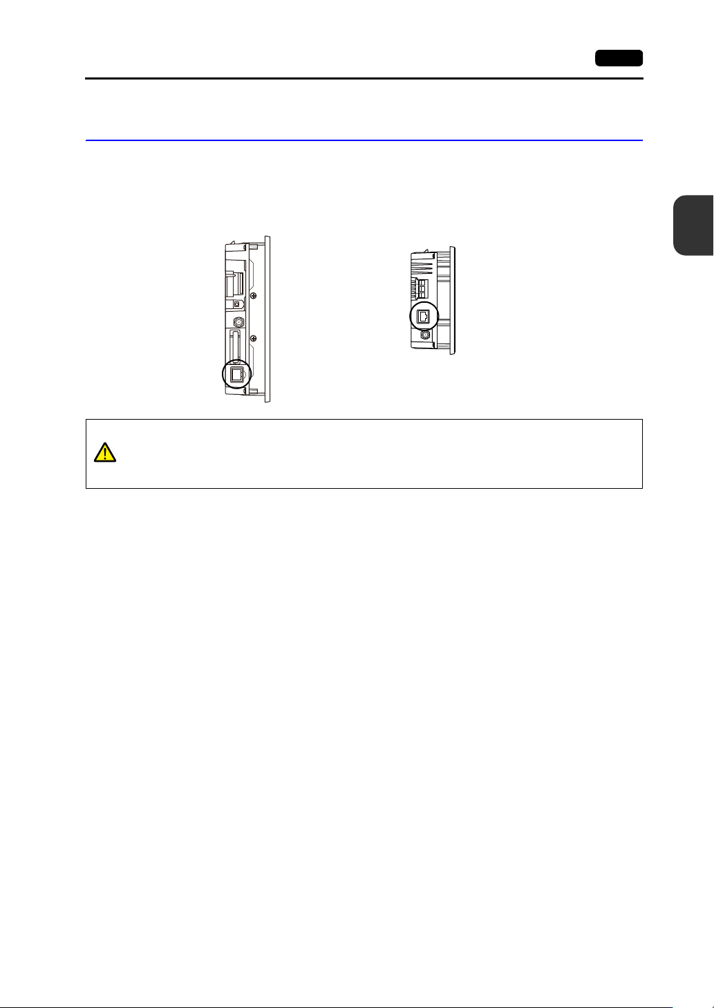
Additional LAN Connector (LAN2)
(Only for Additional Wired LAN I/F Models)
This connector is used for Ethernet communication with controllers and supports 100BASE-TX and
10BASE-T.
The specifications and applications are the same as “ LAN Connector (LAN)” (page 3-20).
Side view
V901xiW
Side view
V907xiW
CAUTION
The MJ1 (or MJ2) and LAN connectors are both 8-pin modular jacks.
Check the connector names on the unit and insert cables into the correct connectors.
Do not connect any peripheral device that will carry excess voltage to the LAN
connector.
3-22 2. Specifications of Components
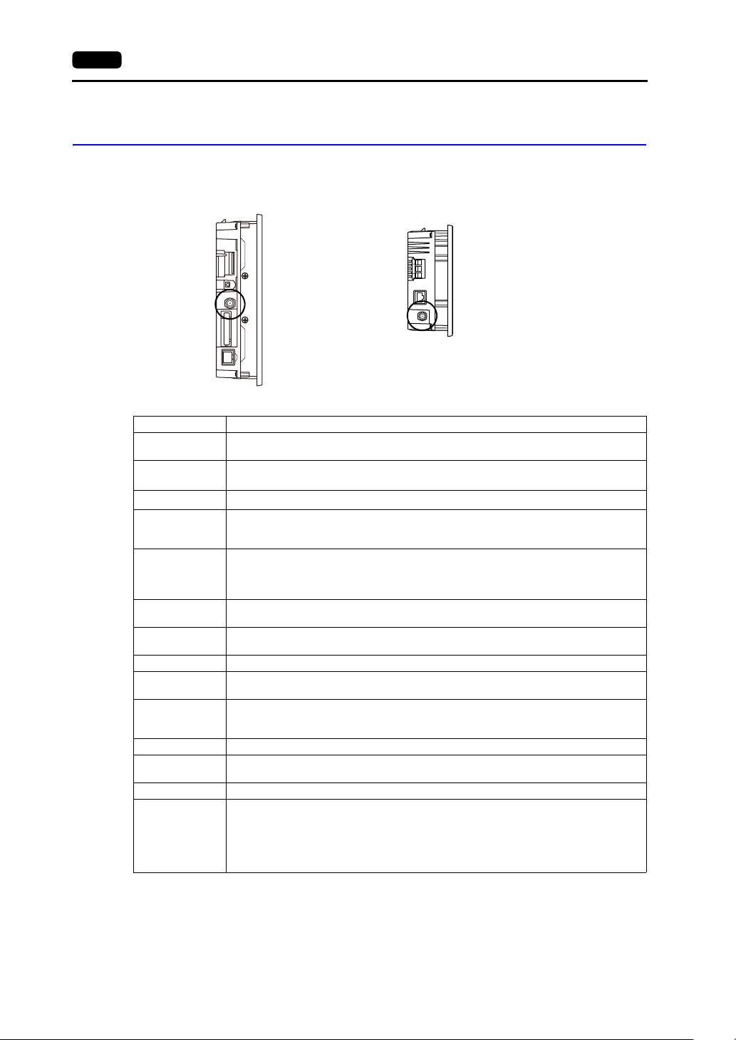
Connector for Wireless LAN Dipole Antenna (WLAN)
(Only for Wireless LAN I/F Models)
This connector is for connecting the external dipole antenna “V9-ANT” (optional) for wireless LAN.
Wireless LAN specifications are shown below.
*1 According to wireless LAN standards, the 2.4 GHz communication frequency band can be used indoors and
outdoors. However, if UL standard certification is required, installation conditions must conform to those
designated by the UL standard.
*2 Channels 1 to 11 which can be used in all countries are enabled. Channels 12 to 14 cannot be used.
*3 The V9 series unit will not conform to the above laws if using any antenna other than the built-in antenna or the
optional V9-ANT for wireless LAN connection.
*4 V9150iXRD, V9120iSRD, V9100iSRD and V9080iSRD conform with only the Japanese Radio Law.
Side view
V901xiW
Side view
V907xiW
Item Specification
Wireless LAN
Standards
IEEE802.11b, IEEE802.11g, IEEE802.11n
Communication
Frequency
*1
2.4 GHz band (2.412 GHz to 2.462 GHz)
Channels
*2
1 to 11 ch (for all countries) (Channel spacing: 5 MHz)
Transmission
Mode
11b: Direct-sequence spread spectrum (DS-SS)
11g: Orthogonal frequency-division multiplexing (OFDM)
11n: Orthogonal frequency-division multiplexing (OFDM)
Transmission
Rate
11b: 1, 2, 5.5, 11 Mbps
11g: 6, 9, 12, 18, 24, 36, 48, 54 Mbps
11n: HT20 (GI: 800 ns) 1 stream: 6.5, 13, 19.5, 26, 39, 52, 58.5, 65 Mbps
11n: HT20 (GI: 400 ns) 1 stream: 7.2, 14.4, 21.7, 29.9, 43.3, 57.8, 65, 72.2 Mbps
Antenna Power
(Output Power)
Max. 10 mW/MHz
Complying
Antennas
Built-in antenna of the V9 series unit
V9-ANT (optional): External dipole antenna for wireless LAN
Polarization Vertical polarization
Horizontal
radiation pattern
Built-in antenna of V9 series unit: Directional
V9-ANT (optional): Omnidirectional
Operation Mode
Infrastructure mode (access point, station)
Ad-hoc mode
* Selected in Local mode.
Authentication OPEN SYSTEM, WPA-PSK, WPA2-PSK
Encryption
Method
NONE, WEP, TKIP, AES
Clients Max. 6 (when the V9 series unit is in access point mode)
Conformance
Standards
*3 *4
TELEC (Japanese Radio Law: Technical Regulations Conformity Certification, Article 2,
clause 1-19)
FCC Part15 SubPart C
IC RSS-210, RSS-Gen
RE: EN300328, EN301489-1, EN301489-17, EN62311, EN60950-1
KC