instruction-manual-product-monitoring-data-acquisition-monitouch-V9-hardware-en.pdf - 第104页
1. Installation Procedure 4-3 4 Installation Installation Conditions Mounting Orientation The V9 series can be mounted in the following or ientations. Panel Cut-out Dimensions (Unit: mm) Upright Example: V9100iS 90 ri…
4-2 1. Installation Procedure
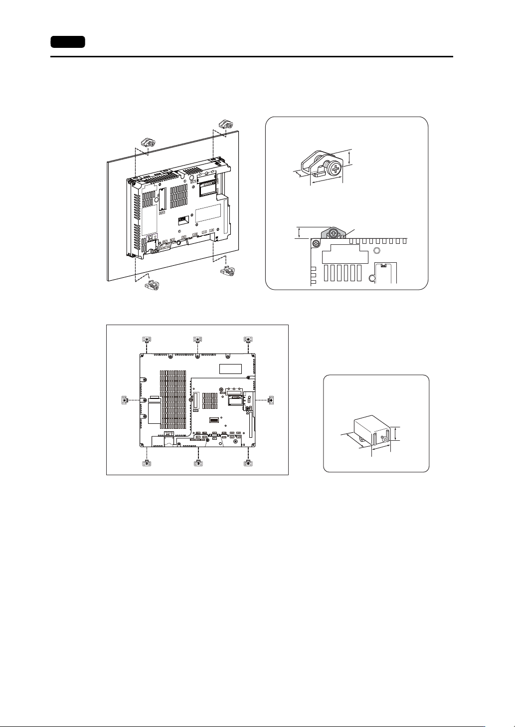
3. Insert the four fixtures provided with the V9 series unit into the mounting holes and tighten them
with the tightening screws (tightening torque: 5.31 Ibf-in (0.6 N·m)).
For the V9150 series, use eight fixtures to mount the unit.
* If the screws are tightened to a torque higher than stated above or the torque at each location
is not equal, the surface sheet may warp due to deformation in the mounting panel and unit.
* When mounting the V9 series unit rotated 90 to the right or left, insert and secure the fixtures
in the same mounting holes shown in the figure below.
* Ground the mounting panel to prevent any buildup of static electricity.
22.0
9.6
9.0
9.6
Fixture dimensions (unit: mm)
Dimensions of a tightened fixture that
protrudes from the edge of the V9 series
unit (unit: mm)
Fall prevention tab
17.8
10.5
30.0
Fixture dimensions
(unit: mm)
1. Installation Procedure 4-3
4
Installation
Installation Conditions
Mounting Orientation
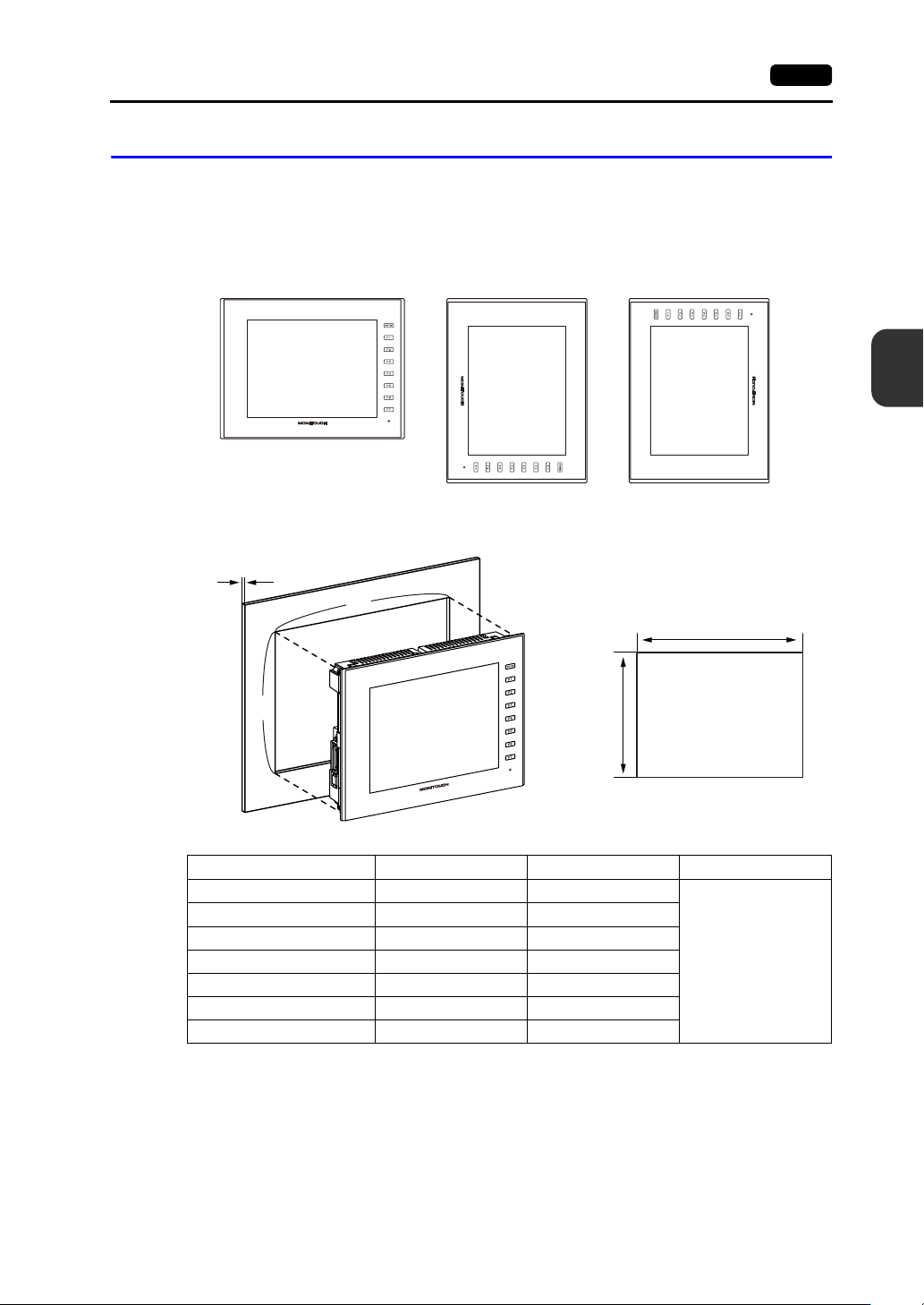
The V9 series can be mounted in the following orientations.
Panel Cut-out Dimensions
(Unit: mm)
Upright
Example: V9100iS
90right
90left
Model X Y Z (panel thickness)
V9150iX
369.4 299.4
1.5 - 4.0
V9120iS
313.0 246.2
V9100iS / V9100iC
289.0 216.2
V910xiW
257.0 183.0
V9080iSD / V9080iCD
220.5 165.5
V907xiW
187.2 133.4
V9060iTD
174.0 131.0
X
Y
X
Y
Z
+0.5
0
+0.5
0
+0.5
0
+0.5
0
+0.5
0
+0.5
0
+0.5
0
+0.5
0
+0.5
0
+0.5
0
+0.5
0
+0.5
0
+0.5
0
+0.5
0
4-4 1. Installation Procedure
Mounting Spatial Restrictions
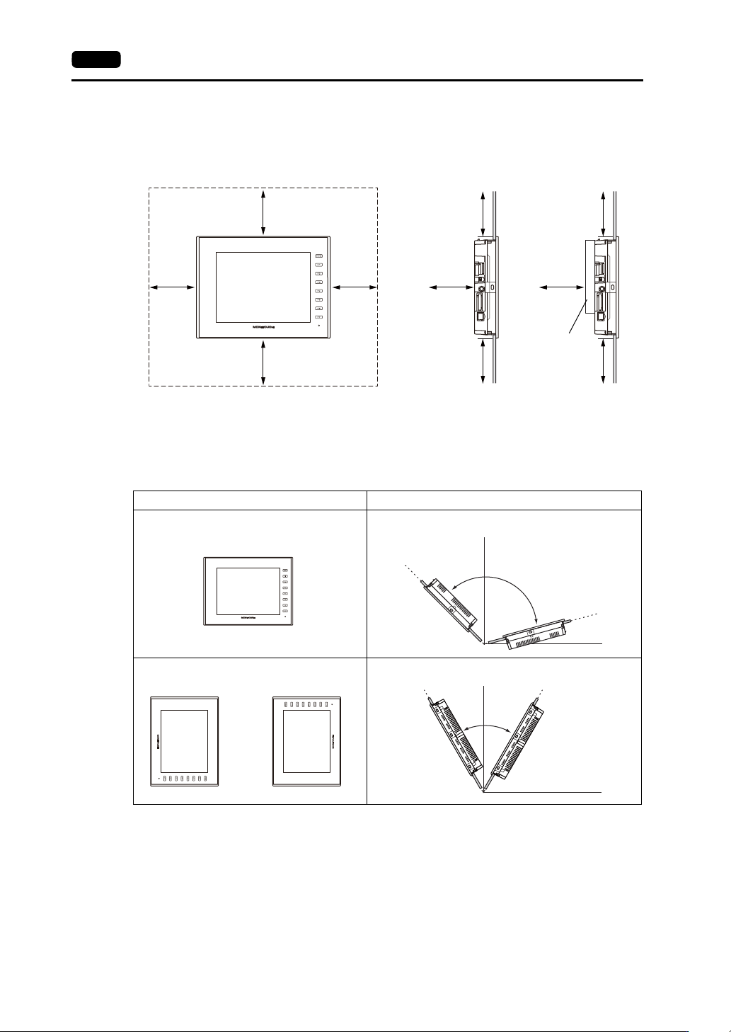
Mount the V9 series unit with approximately 100 mm of space around the periphery of the unit.
Mounting Angle
The mounting angle differs depending on the mounting orientation. Mount the unit within the angle
ranges shown in the table below.
* When supplying power externally from a modular jack (MJ1/MJ2) or USB-A, mount the V9 series
unit at an angle between 60 and 120.
Ambient Temperature
Use the V9150 series in an ambient temperature range of 0 °C to +40 °C (wet-bulb temperature of
39 °C or less).
Regarding other models, use in a range of 0 °C to +50 °C (wet-bulb temperature of 39 °C or less).
100 100
100
100 100
100 100
100
100 100
Front view Side view
With communication
I/F unit/optional
units installed
(Unit: mm)
Mounting Orientation Mounting Angle
Upright
0°
135°
90°
15°
D
i
s
p
l
a
y
D
i
s
p
l
a
y
90right
90 left
or
0°
90°
60°120°
D
i
s
p
l
a
y
D
i
s
p
l
a
y