instruction-manual-product-monitoring-data-acquisition-monitouch-V9-hardware-en.pdf - 第98页
3 2. Specifications of Components 3-33 Names and Specifications of Components DUR-00 The unit is equipped with DIP switches 1 to 4. T u rn OFF power to the unit before cha nging any DIP switches. Upon delivery , all DIP …
3-32 2. Specifications of Components
V907xiW, V9060iTD Series
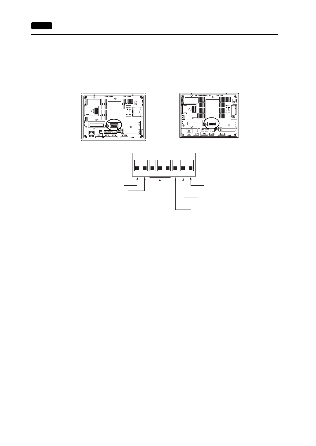
The V9 series unit is equipped with DIP switches 1 to 8. Turn OFF power to the unit before changing
any DIP switches.
Upon delivery, all DIP switches are set to OFF.
* Only for V907xiW
DIPSW1 (Storage Automatic Upload)
Set DIPSW1 to ON to automatically upload screen programs from a storage device such as an SD
card or USB flash drive.
Refer to “DIP Switches (DIPSW)” (page 3-30) for the procedure.
DIPSW2 (Display of Touch Switch Test Screen) Only for V907xiW.
Set DIPSW2 to ON to check if touch switches are functioning properly.
Refer to “DIPSW2 (Display of Touch Switch Test Screen) For V910xiW Only” (page 3-31) for the
procedure.
* Touch switch adjustment is available for the V9070iW (analog resistive film type).
For details on touch switch adjustment, refer to the V9 Series Troubleshooting/Maintenance Manual.
DIPSW 3, 4, 5 (Not Used)
Set these DIP switches to OFF.
DIPSW 6, 7, 8 (Terminating Resistance Setting)
Connection at MJ1 via RS-232C and RS-485 (2-wire connection) is possible. Turn DIPSW6 to ON
for the following situations.
- Master station for multi-link2 connection
- Connection to a controller (PLC, temperature controller, etc.) via RS-485
- At the termination of V-link connection via RS-485
Connection at MJ2 via RS-232C, RS-422 (4-wire connection), or RS-485 (2-wire connection) is
possible.
When connecting via RS-485 (2-wire connection), set DIPSW8 to ON. When connecting via
RS-422 (4-wire connection), set DIPSW7 and 8 to ON.
Rear view
V907xiW
Rear view
V9060iTD
ON
12345678
Storage automatic upload
MJ2 (modular jack 2):
+SD/-SD terminating resistance
MJ1 (modular jack 1): terminal resistance
MJ2 (modular jack 2):
+RD/-RD terminating resistance
Not used
Display of touch switch test screen
*
3
2. Specifications of Components 3-33
Names and Specifications of Components
DUR-00
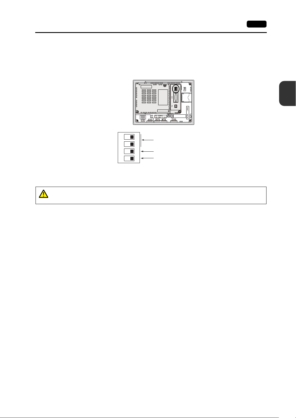
The unit is equipped with DIP switches 1 to 4. Turn OFF power to the unit before changing any DIP
switches.
Upon delivery, all DIP switches are set to OFF.
DIPSW 1, 2 (Terminating Resistance Setting)
When connecting a controller to CN1 via RS-422/485 (2-wire connection), set DIPSW1 to the ON
position.
When connecting a controller to CN1 via RS-422/485 (4-wire connection), set DIPSW1 and 2 to
the ON position.
Rear view
ON
1234
Not used
CN1: +RD/-RD terminating resistance at pins 1 and 2
CN1: +SD/-SD terminating resistance at pins 3 and 4
CAUTION
When connecting a controller to CN1 via RS-232C, set DIPSW1 and 2 to the OFF
position.
3-34 2. Specifications of Components
Please use this page freely.