instruction-manual-product-monitoring-data-acquisition-monitouch-V9-hardware-en.pdf - 第105页
4-4 1. Installation Procedure Mounting Spatial Restrictions Mount the V9 series unit with approximately 100 mm of space around the periphery of the unit. Mounting Angle The mounting angle differs depending on the mount i…
1. Installation Procedure 4-3
4
Installation
Installation Conditions
Mounting Orientation
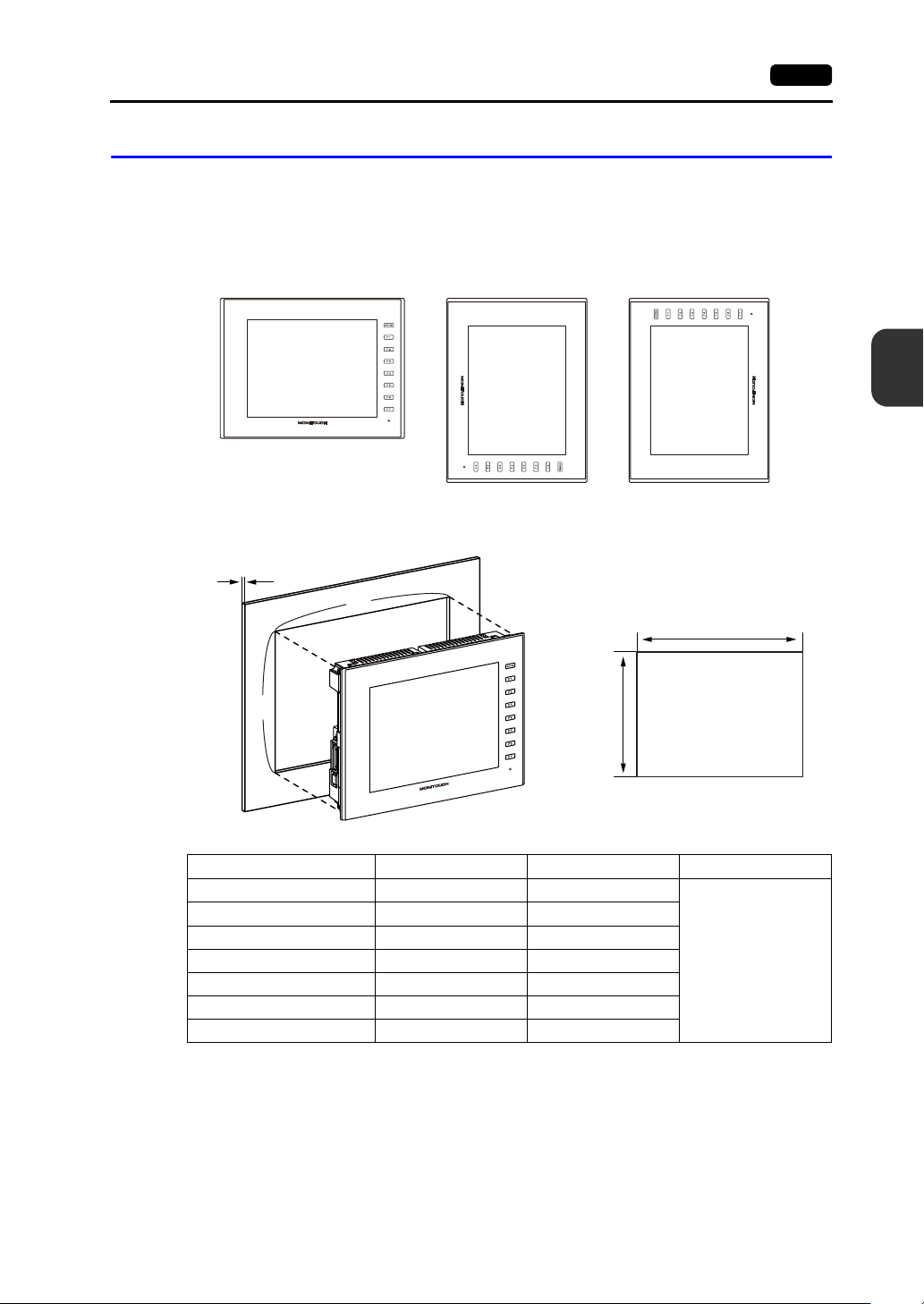
The V9 series can be mounted in the following orientations.
Panel Cut-out Dimensions
(Unit: mm)
Upright
Example: V9100iS
90right
90left
Model X Y Z (panel thickness)
V9150iX
369.4 299.4
1.5 - 4.0
V9120iS
313.0 246.2
V9100iS / V9100iC
289.0 216.2
V910xiW
257.0 183.0
V9080iSD / V9080iCD
220.5 165.5
V907xiW
187.2 133.4
V9060iTD
174.0 131.0
X
Y
X
Y
Z
+0.5
0
+0.5
0
+0.5
0
+0.5
0
+0.5
0
+0.5
0
+0.5
0
+0.5
0
+0.5
0
+0.5
0
+0.5
0
+0.5
0
+0.5
0
+0.5
0
4-4 1. Installation Procedure
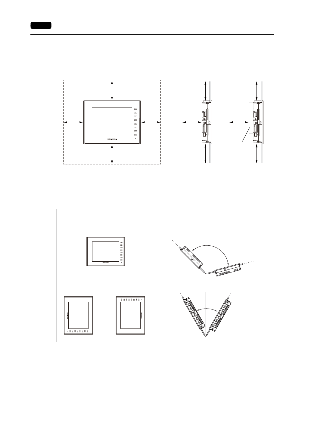
Mounting Spatial Restrictions
Mount the V9 series unit with approximately 100 mm of space around the periphery of the unit.
Mounting Angle
The mounting angle differs depending on the mounting orientation. Mount the unit within the angle
ranges shown in the table below.
* When supplying power externally from a modular jack (MJ1/MJ2) or USB-A, mount the V9 series
unit at an angle between 60 and 120.
Ambient Temperature
Use the V9150 series in an ambient temperature range of 0 °C to +40 °C (wet-bulb temperature of
39 °C or less).
Regarding other models, use in a range of 0 °C to +50 °C (wet-bulb temperature of 39 °C or less).
100 100
100
100 100
100 100
100
100 100
Front view Side view
With communication
I/F unit/optional
units installed
(Unit: mm)
Mounting Orientation Mounting Angle
Upright
0°
135°
90°
15°
D
i
s
p
l
a
y
D
i
s
p
l
a
y
90right
90 left
or
0°
90°
60°120°
D
i
s
p
l
a
y
D
i
s
p
l
a
y
2. Power Supply Cable and Grounding Connections 4-5
4
Installation
2. Power Supply Cable and Grounding
Connections
Power Supply Cable Connection
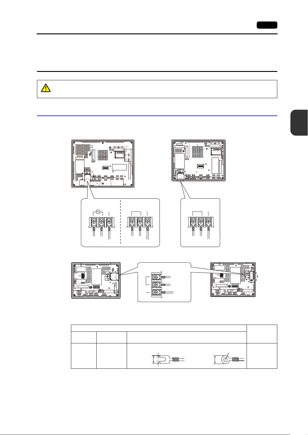
Connect the power supply cable to the terminal on the backside of the unit.
For information on the specifications of the power supply cable and the tightening torque of the
screws on the power supply terminal block, refer to the following table.
DANGER
There is a risk of electrical shock.
Shut the power off before connecting the power supply cable.
LNFG
+−
24V DC
FG
+−
24V DC
FG
100V-240VAC 24VDC 24VDC
+
−
24V DC
FG
24VDC
Power supply
Grounding
Power supply
Grounding
V9150, V9120, V9100 V910xiW, V9080
Grounding
Power supply
V907xiW
Grounding
Power
supply
V9060iTD
Terminal Screw
Power Supply
Cable
Screw
Size
Tightening
Tor que
Crimp-style Terminal
M3.5
7.1 to 8.8
lbf-in
(0.8 to 1.0
N·m)
AWG16 to 14
3.7 mm
7.1 mm
or less
7.1 mm
or less
3.7 mm