instruction-manual-product-monitoring-data-acquisition-monitouch-V9-hardware-en.pdf - 第85页
3-20 2. Specifications of Components LAN Connector (LAN) This connector is used for Ethernet communication with controllers and supports 100BASE-TX and 10BASE-T . The LAN connector pins correspond to the signals as shown…
3
2. Specifications of Components 3-19
Names and Specifications of Components
Notes
A maximum of two USB hubs can be connected (cascaded) to the V9 series unit.
Note that performance will decrease when two USB hubs are connected.
Do not turn off the power adaptor or disconnect the connector between the power adaptor and
the USB hub when the USB hub is connected to the V9 series unit and powered by the
adaptor.
Doing so may prevent sufficient power supply to the V9 series unit resulting in faulty operation
such as repeated restarting.
When connecting two USB hubs to the V9 series unit, supply power to each USB hub using
the adaptor provided with each hub.
Even when connecting only one USB hub, use the provided power supply adaptor (if
provided).
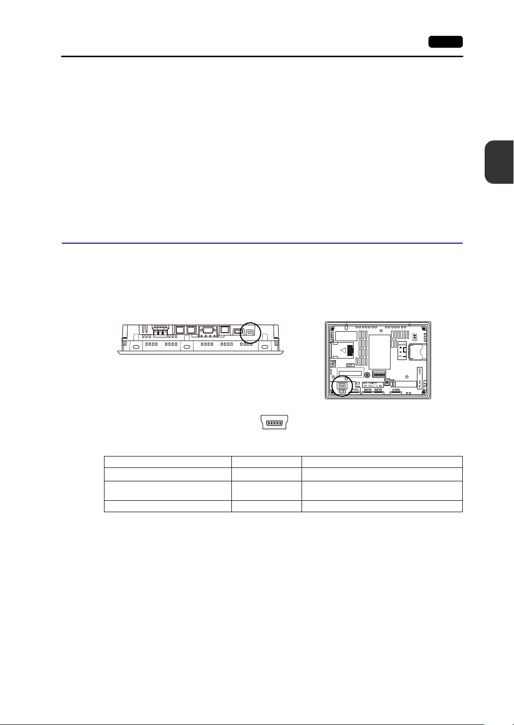
USB mini-B (Slave Port)
This connector is used for screen program transfer or connection with a PictBridge-compatible printer.
The USB mini-B port of the V9 unit complies with USB version 2.0.
Applications
*1 The ladder transfer function cannot be used simultaneously with 1:n communication (multi-drop) or multi-link
communication.
Bottom view
V9100
Rear view
V907xiW
Enlarged view
Application V-SFT-6 Setting Refer to
Ladder transfer function
*1
Required V9 Series Reference Manual 2
PictBridge-compatible printer
connection
Required V9 Series Reference Manual 1
Screen program transfer Required V9 Series Setup Manual
3-20 2. Specifications of Components
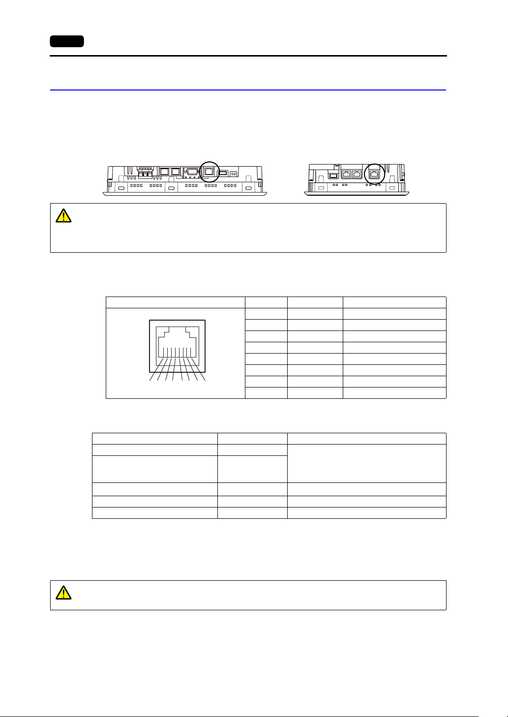
LAN Connector (LAN)
This connector is used for Ethernet communication with controllers and supports 100BASE-TX and
10BASE-T.
The LAN connector pins correspond to the signals as shown below.
Specification: IEEE802.3 (u)-compliant, UDP/IP and TCP/IP support, Auto-MDIX and
Auto-Negotiation function support
Applications
*1 The ladder transfer function cannot be used simultaneously with 1:n communication (multi-drop) or multi-link
communication.
Wiring
Use a commercially available cable. Using a custom-made cable may prevent normal connection to
the network.
Recommended cable: 100 UTP (unshielded twist-pair) cable, category 5, max. 100 m long
* Both straight and cross cables are usable, irrespective of the presence or absence of a hub.
Bottom view Bottom view
V9100 V907xiW
CAUTION
The MJ1 (or MJ2) and LAN connectors are both 8-pin modular jacks.
Check the connector names on the unit and insert cables into the correct connectors.
Do not connect any peripheral device that will carry excess voltage to the LAN
connector.
LAN Pin No. Signal Description
1 TX+ Ethernet send signal (+)
2TX Ethernet send signal ()
3 RX+ Ethernet receive signal (+)
4 NC Not used
5 NC Not used
6RX Ethernet receive signal ()
7 NC Not used
8 NC Not used
8 76 5 43 21
Application V-SFT-6 Setting Refer to
PLC/temperature controller connection Required
V9 Series Connection Manual
Multi-link2 (Ethernet)/
1:n Multi-link2 (Ethernet)
communication
Required
Ladder transfer function
*1
Required V9 Series Reference Manual 2
Screen program transfer Required V9 Series Setup Manual
Ethernet communication function Required V9 Series Reference Manual 2
CAUTION
When using the LAN port, keep the LAN cable away from the power supply cable as
much as possible.
3
2. Specifications of Components 3-21
Names and Specifications of Components
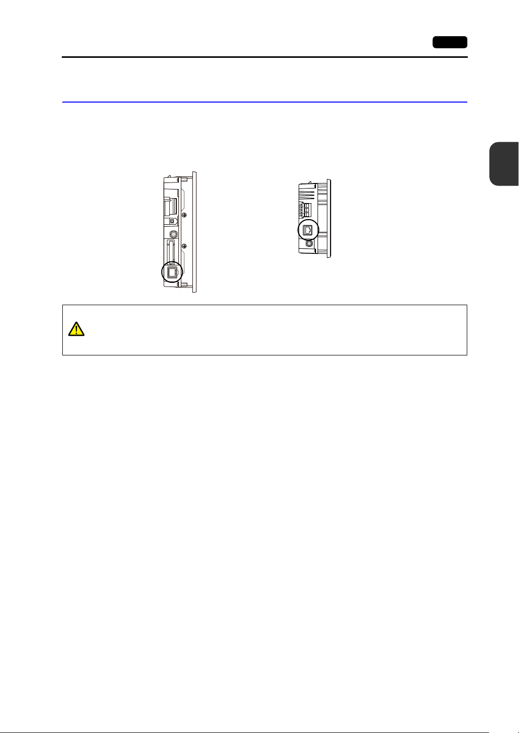
Additional LAN Connector (LAN2)
(Only for Additional Wired LAN I/F Models)
This connector is used for Ethernet communication with controllers and supports 100BASE-TX and
10BASE-T.
The specifications and applications are the same as “ LAN Connector (LAN)” (page 3-20).
Side view
V901xiW
Side view
V907xiW
CAUTION
The MJ1 (or MJ2) and LAN connectors are both 8-pin modular jacks.
Check the connector names on the unit and insert cables into the correct connectors.
Do not connect any peripheral device that will carry excess voltage to the LAN
connector.