instruction-manual-product-monitoring-data-acquisition-monitouch-V9-hardware-en.pdf - 第108页
3. Securing USB Cables 4-7 4 Installation 3. Securing USB Cables USB cables may disconnect from the V9 seri es unit depending on the mounting conditions. Use the cable tie provided with the unit to prevent discon nection…
4-6 2. Power Supply Cable and Grounding Connections
Notes on the Power Supply
The power supply must be used within allowable range of voltage fluctuation.
Use a power supply with low noise between cables and between the ground and cables.
Use the thickest power supply cable possible that is twisted to minimize drops in voltage.
Keep power supply cables away from high-voltage, large-current carrying cables.
When using models V9101iW or V9071iW (capacitive type touch panel), use a Class 2 power
supply for a 24-VDC input.
Notes on Usage of the 100 to 240 VAC Specification
The V9 series is an overvoltage category II product.
While the use of an isolating transformer generally improves noise resistance, if the V9 series unit
is a significant distance from the secondary port of the transformer or noise interference occurs
easily, an isolating transformer is ineffective.
If any power voltage fluctuation caused by noise is expected, the use of a voltage stabilizer
(effective for noise resistance) is recommended.
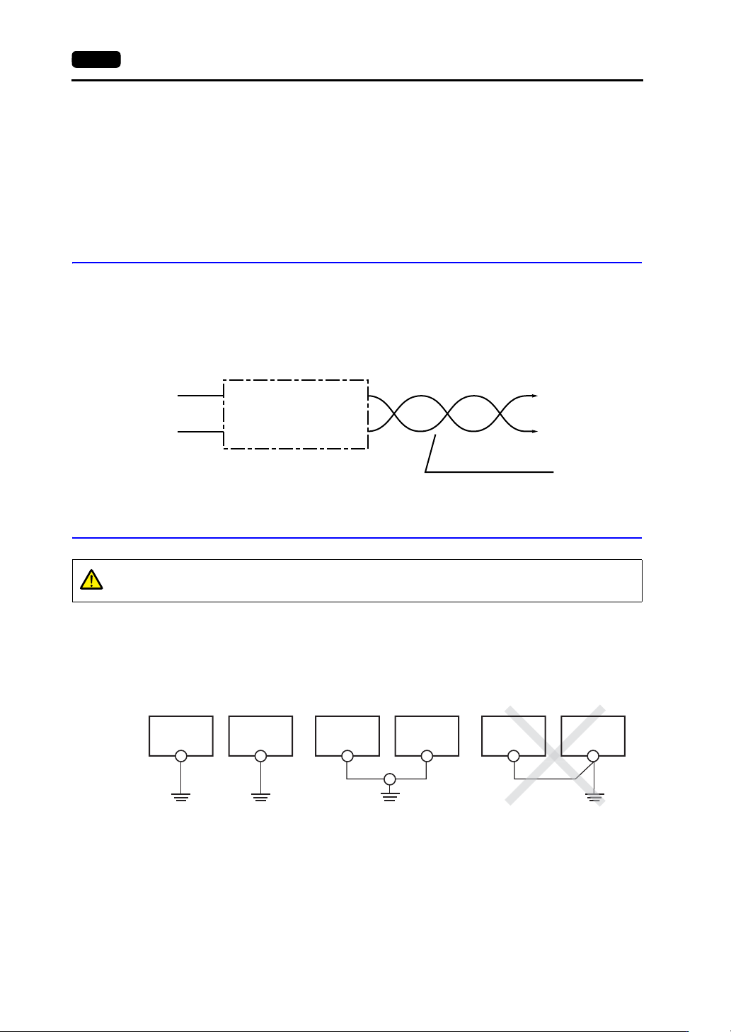
Grounding
An independent grounding must be used for the unit.
Use a grounding cable with a nominal cross section of more than 2 mm
2
.
Set the grounding point near the unit to shorten the distance of grounding cables.
The signal ground (SG) and frame ground (FG) are connected inside the V9150 series unit.
* For models V9101iW and V9071iW (capacitive type touch panel), use independent grounding.
Power supply
Insulation transformer or
stabilized transformer
To V9 series unit
1.25 mm
2
Twist the cables.
CAUTION
Always ground the V9 series.
(The level of grounding resistance should be less than 100 .)
V9 series
unit
Other
equipment
V9 series
unit
Other
equipment
V9 series
unit
Other
equipment
Independent grounding (best)
*
Shared grounding (good) Cross grounding (prohibited)
Grounding resistance:
less than 100
Grounding resistance:
less than 100
3. Securing USB Cables 4-7
4
Installation
3. Securing USB Cables
USB cables may disconnect from the V9 series unit depending on the mounting conditions.
Use the cable tie provided with the unit to prevent disconnection.
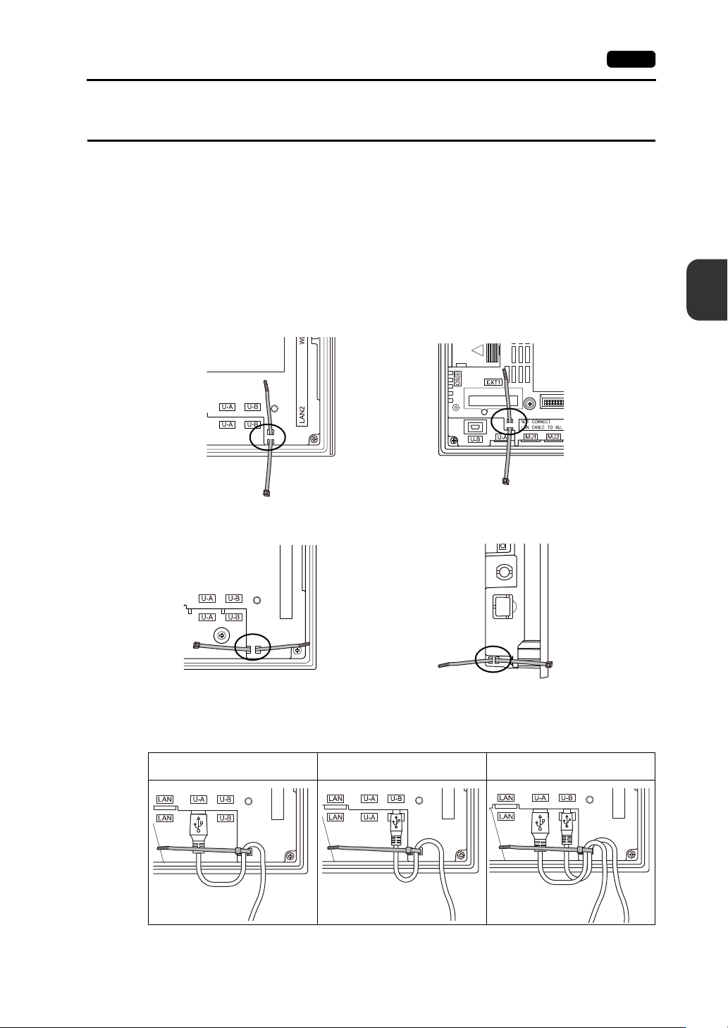
Securing USB Cables
1. Preparing a cable tie
Pass a cable tie through the hole as shown in the figure below.
* For the V910xiW, V907xiW and V9060iTD, pass the cable tie through the lower side upward.
For the V9150, V9120 and V9100, pass the cable tie through the hole from left to right.
For the V9080, pass the cable tie through the hole from right to left.
2. Inserting and securing a USB cable
Insert a USB cable and secure it using the cable tie.
Example:
When only USB-A is used When only USB mini-B port is used
When both USB-A and USB mini-B
(two cables) are used
Rear view
Side view
V910xiW
V9080
Rear view
V907xiW and V9060iTD
Rear view
V9150, V9120 and V9100
4-8 4. Inserting and Removing SD Cards
4. Inserting and Removing SD Cards
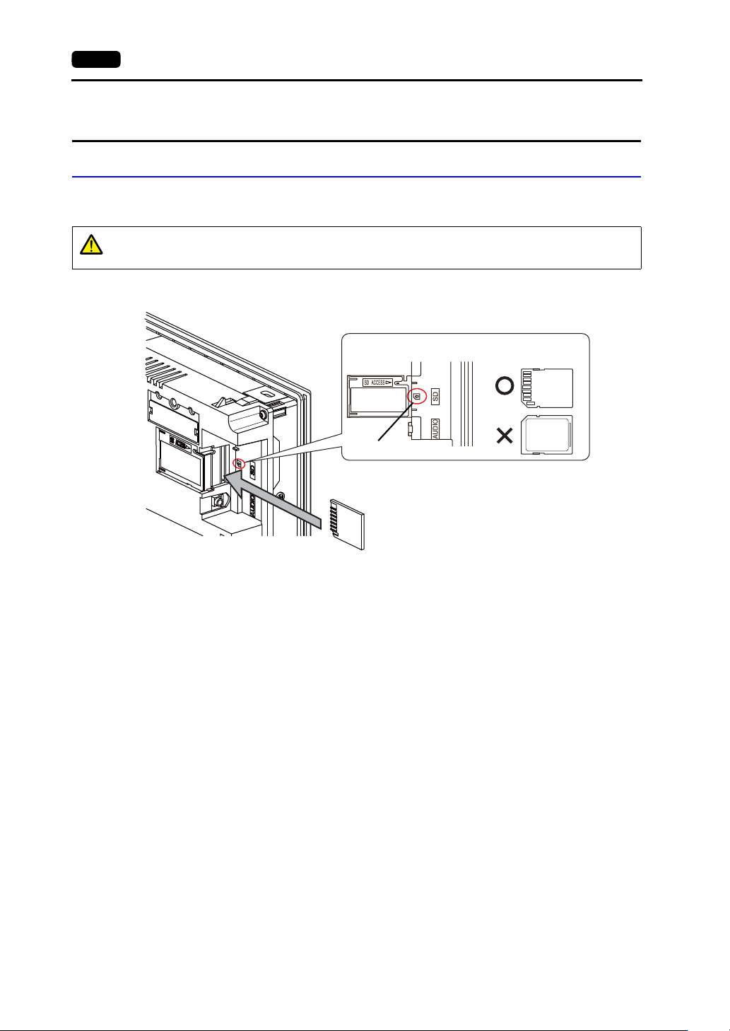
SD Card Insertion/Removal Procedure
1. Hold the SD card in the same orientation (SD card rear) as shown by the SD card pictured on the
unit and then insert the SD card into the slot until it clicks.
2. Check that the SD card access LED is unlit before removing the SD card. Push the SD card until it
clicks and then the SD card will come out. Pinch the SD card with your fingers and remove it from
the slot.
* When removing the SD card, select [Storage Removal] in the system menu, or press the
[Storage Removal] switch.
CAUTION
Insert the SD card into the V9 series unit in the correct orientation.
Failure to do so may damage the SD card or the slot on the unit.
SD card
Enlarged view
SD card picture
SD card orientation
Rear
Front
Rear
Example: V910xiW