instruction-manual-product-monitoring-data-acquisition-monitouch-V9-hardware-en.pdf - 第92页
3 2. Specifications of Components 3-27 Names and Specifications of Components SD Card Interface (SD) This is the interface used for inserting an SD card. An SD card can be used to transfer screen programs and save log da…

3-26 2. Specifications of Components
Optional Unit Connector (EXT2) (V910xiW/Standard Models Only)
This is a connector for attaching the optional “GUR-xx” unit.
The types of optional units are shown below.
* For details on specifications and how to attach an optional unit, refer to the respective instruction
manual.
Type Communication Specification
GUR-00 Video input 4 CH
GUR-01 RGB input 1 CH
GUR-02 RGB output 1 CH
GUR-04 Video input 1 CH
GUR-10 Video input 1 CH and RGB input 1 CH
GUR-11 RGB input 2 CH
Rear view Rear view
V9100iS V9080iS
3
2. Specifications of Components 3-27
Names and Specifications of Components
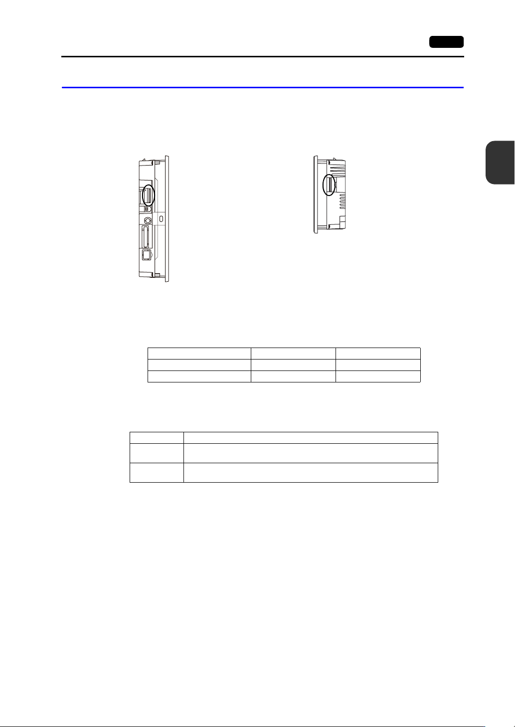
SD Card Interface (SD)
This is the interface used for inserting an SD card.
An SD card can be used to transfer screen programs and save log data and image data.
SD Card Specifications
SD cards that are compatible with the V9 series are shown below.
* This manual collectively refers to the following cards as “SD cards”.
SD Card Access LED
The state of the SD card access LED is configured as shown below.
Applications
For details on functions that use an SD card, refer to the separate V9 Series Reference Manual 2.
For details on reading and writing between an SD card and the V9 series unit, refer to the separate
V9 Series Troubleshooting/Maintenance Manual.
Side view
Side view
V9100
V907xiW
Card Type Capacity File System
SD card 2 GB max. FAT, FAT32
SDHC card 4 GB to 32 GB FAT32
LED Description
Off
The SD card is not being accessed.
The SD card can be removed.
Flashing red
The SD card is being accessed.
The LED turns off when access is complete.

3-28 2. Specifications of Components
Notes on SD Card Handling
1. The SD card access LED flashes red when the SD card is being accessed. Do not remove the SD
card while the LED is flashing. Doing so may destroy data on the SD card.
2. When removing the SD card, check that the SD card access LED has turned off, then select
[Storage Removal] in the system menu, or press the [Storage Removal] switch.
3. Do not turn off power to the unit when the SD card is being accessed.
4. Make a backup copy of the SD card at regular intervals.
5. If a disk error occurs and data read/write operations are disabled, execute ScanDisk on Windows
and try to restore the disk.
If the disk cannot be restored, format the device. Note that formatting will completely erase all
stored data. (For information on executing ScanDisk on Windows, refer to the relevant Windows
manual.)
6. SD cards have a limited number of write cycles. Consequently, frequent writing at short intervals
may shorten the service life of SD cards. When using an SD card to save logging/alarm data, take
the logging time/monitoring intervals into consideration. Also, avoid repeated writing using the
CYCLE macro command.