instruction-manual-product-monitoring-data-acquisition-monitouch-V9-hardware-en.pdf - 第109页
4-8 4. Inserting and Removing SD Cards 4. Inserting and Removing SD Cards SD Card Insertion/Removal Procedure 1. Hold the SD card in the same orientation (SD ca rd rear) as shown by the SD card pictured on the unit and t…
3. Securing USB Cables 4-7
4
Installation
3. Securing USB Cables
USB cables may disconnect from the V9 series unit depending on the mounting conditions.
Use the cable tie provided with the unit to prevent disconnection.
Securing USB Cables
1. Preparing a cable tie
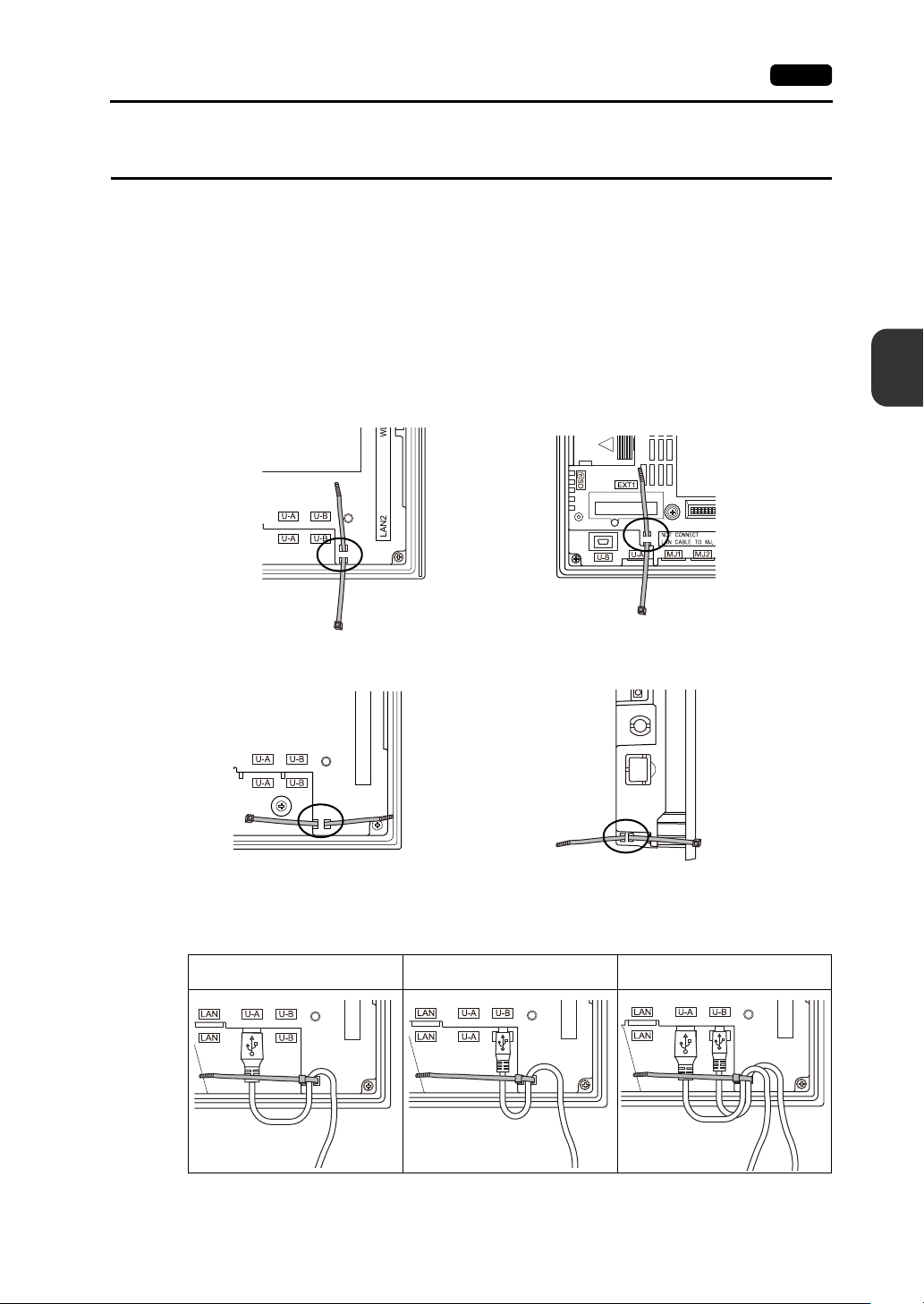
Pass a cable tie through the hole as shown in the figure below.
* For the V910xiW, V907xiW and V9060iTD, pass the cable tie through the lower side upward.
For the V9150, V9120 and V9100, pass the cable tie through the hole from left to right.
For the V9080, pass the cable tie through the hole from right to left.
2. Inserting and securing a USB cable
Insert a USB cable and secure it using the cable tie.
Example:
When only USB-A is used When only USB mini-B port is used
When both USB-A and USB mini-B
(two cables) are used
Rear view
Side view
V910xiW
V9080
Rear view
V907xiW and V9060iTD
Rear view
V9150, V9120 and V9100
4-8 4. Inserting and Removing SD Cards
4. Inserting and Removing SD Cards
SD Card Insertion/Removal Procedure
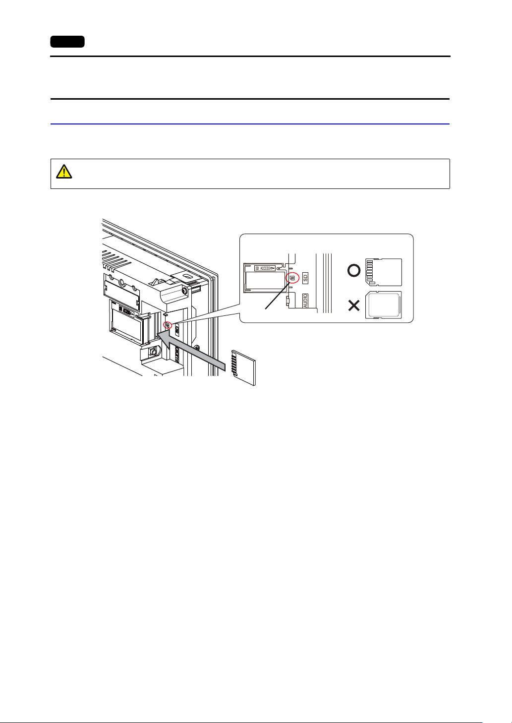
1. Hold the SD card in the same orientation (SD card rear) as shown by the SD card pictured on the
unit and then insert the SD card into the slot until it clicks.
2. Check that the SD card access LED is unlit before removing the SD card. Push the SD card until it
clicks and then the SD card will come out. Pinch the SD card with your fingers and remove it from
the slot.
* When removing the SD card, select [Storage Removal] in the system menu, or press the
[Storage Removal] switch.
CAUTION
Insert the SD card into the V9 series unit in the correct orientation.
Failure to do so may damage the SD card or the slot on the unit.
SD card
Enlarged view
SD card picture
SD card orientation
Rear
Front
Rear
Example: V910xiW
5. Installing the Battery 4-9
4
Installation
5. Installing the Battery
Role of the Battery
The battery provides backup power to the user memory area in SRAM (non-volatile device $L and
$LD, sampling data) as well as the built-in clock.
Battery Replacement Period
The service life of the battery is about 5 years from the date of manufacture.
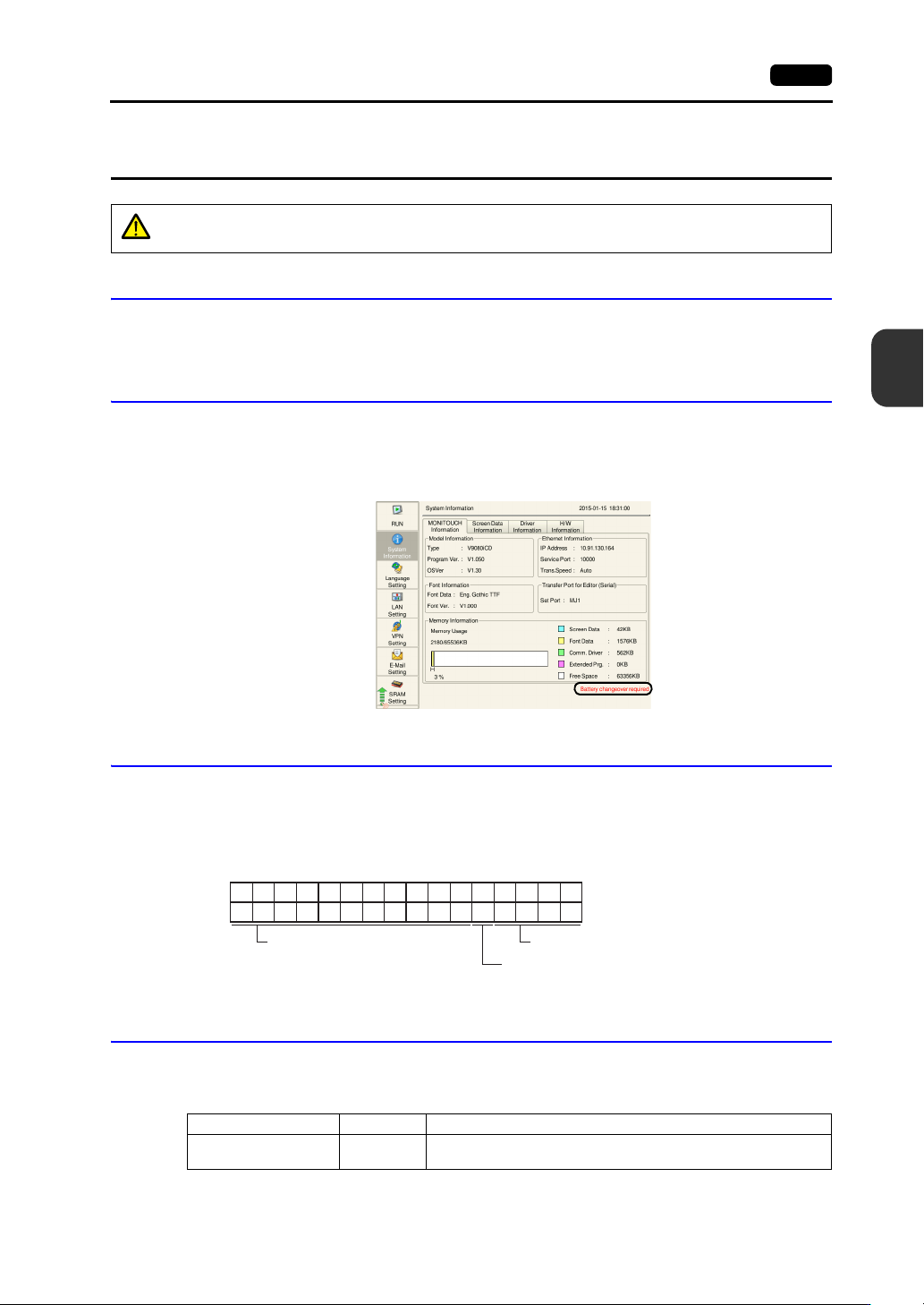
When the battery voltage drops, the message “Battery changeover required” appears at the lower right
in the Local mode on the V9 series unit.
* For information on the Local mode, refer to the separate V9 Series Troubleshooting/Maintenance Manual.
Battery Voltage Drop Detection
The battery status is output to the internal device memory address $s167 of the V9 series unit.
When the battery voltage drops, the 4th bit of $s167 turns ON.
If the battery voltage drops (4th bit turns ON) within the expiration date (five years), replace the battery
immediately.
Battery Replacement
Replacement batteries are available from Hakko Electronics.
V9150, V9120, V9100, V910xiW, V9080 series
* When using a commercially available battery, use “CR2450S”.
CAUTION
A battery is already installed upon delivery.
$s167
15 14 13 12 11 10 09 08 07 06 05 04 03 02 01 00
0000000000 0
MSB LSB
0000
System reserved (setting: 0)
0: Battery OK.
1: Battery voltage drop, no battery
System reserved (setting: 0)
Name Model Description
Battery for replacement V9-BT
Coin-type lithium primary cell 1 pce.
Caution sticker 1 pce.