00198711-01_UM_X-Serie-S_EN.pdf - 第113页
Instruction manual SIPLACE X-Series 3 Technical data and assemblies From software version 713.0 Edition 11/2019 3.3 Dimensions and weig ht 113 3.3.2 For a definition of placement performance values 3 Fig. 3.3 - 3 Maneuve…
3 Technical data and assemblies Instruction manual SIPLACE X-Series
3.3 Dimensions and weight From software version 713.0 Edition 11/2019
112
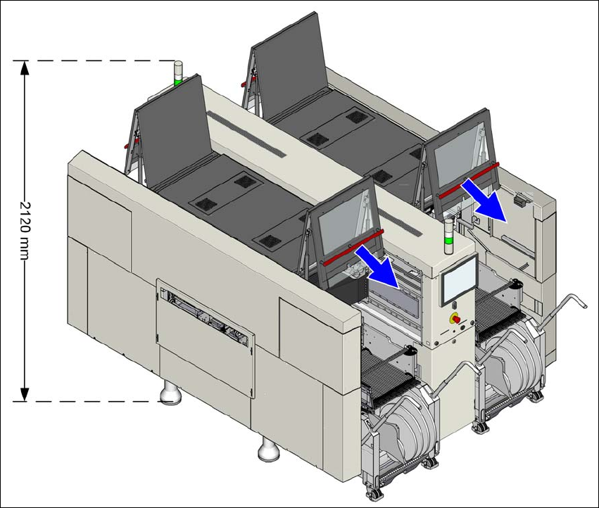
3.3.1.2 Height of the folded up protective cover
3
Fig. 3.3 - 2 Height of the folded-up protective cover - dimensions in millimeters (example of SIPLACE X4i S shown)
The specified dimensions refer to the max. PCB conveyor height of 950 mm.
(1) The height varies according to the set PCB conveyor height
– for PCB conveyor height 900 mm = 195 mm ± 15 mm
– for PCB conveyor height 930 mm = 225 mm ± 15 mm
– for PCB conveyor height 950 mm = 245 mm ± 15 mm
Instruction manual SIPLACE X-Series 3 Technical data and assemblies
From software version 713.0 Edition 11/2019 3.3 Dimensions and weight
113
3.3.2 For a definition of placement performance values
3
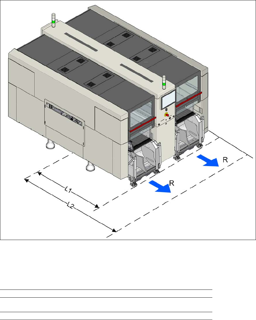
Fig. 3.3 - 3 Maneuvering distances of component trolleys in X-Series S placement machines
The maneuvering distances R for the component trolley of the SIPLACE X-Series S placement
machines are as follows:
3
3
3
Maneuvering distance R location position 600 mm
Distance L1: Machine center to outer edge of X component
trolley
1470 mm
Distance L2: Machine center to wall 2070 mm
3 Technical data and assemblies Instruction manual SIPLACE X-Series
3.3 Dimensions and weight From software version 713.0 Edition 11/2019
114
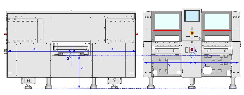
3.3.3 Center of gravity
3
Fig. 3.3 - 4 Center of gravity in millimeters (example of SIPLACE X2 S / X3 S / X4 S shown)
X coordinate 1400 mm
Y coordinate 1050 mm
Z coordinate 630 mm
These center of gravity coordinates relate to placement machines with a PCB conveyor height of
930 mm.