00198711-01_UM_X-Serie-S_EN.pdf - 第335页
Instruction manual SIPLACE X-Series S 6 Station extensions From software version 713.0 Edition 11/2019 6.9 Stationary cameras 335 6.9.2 St ationary component camera P&P , type 33 GigE Item no. 03105198- xx S tationar…

6 Station extensions Instruction manual SIPLACE X-Series S
6.9 Stationary cameras From software version 713.0 Edition 11/2019
334
6.9.1.2 Technical data
6
Component dimensions 0.2 mm x 0.2 mm up to 16 mm x 16 mm for single component
measurement
Component range 0402 to SO, PLCC, QFP, sockets, plugs, BGA, special components,
bare dies, flip-chips, shields
Min. lead pitch 0.25 mm
Min. lead width 0.1 mm
Min. ball pitch 0.14 mm
Min. ball diameter 0.08 mm
Field of vision 19.4 mm x 19.4 mm
Illumination type Front-illumination (6 levels, programmable as required)
Instruction manual SIPLACE X-Series S 6 Station extensions
From software version 713.0 Edition 11/2019 6.9 Stationary cameras
335
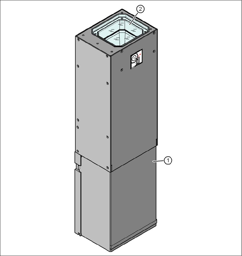
6.9.2 Stationary component camera P&P, type 33 GigE
Item no. 03105198-xx Stationary camera for the CPP head, type 33 GigE
6
Fig. 6.9 - 2 Design of stationary component camera P&P, type 33 GigE
(1) Camera housing with integral camera and camera amplifier
(2) Glass plate - illumination and lens levels below
6 Station extensions Instruction manual SIPLACE X-Series S
6.10 IPC-Hermes-9852 From software version 713.0 Edition 11/2019
336
6.9.2.1 Safety instructions
6
6.9.2.2 Technical data
6
6
6.10 IPC-Hermes-9852
IPC-HERMES-9852 is a communication protocol for SMT lines and can replace the IPC SMEMA
interface. This protocol allows you to transfer more information than previously via the IPC
SMEMA interface.
This could be, for example:
– Unique board IDs
– Barcodes
– Conveyor speed,
– Board length and width
– Board thickness
– Transport clearance height
All this information can be transmitted along the whole line without interruption.
For a detailed description, see the Administrator Manual IPC-HERMES-9852, item no.
[00198615-xx].
WARNING
Risk of collisions!
When changing the placement head from a TwinStar/VHF to a SpeedStar, the SpeedStar
collides with the camera housing.
Dismantle the stationary component camera for the TwinStar.
When changing the placement head from a TwinStar to a SIPLACE MultiStar CPP,
the stationary component camera is fitted in the bottom position.
Component dimensions 0.5 mm x 0.5 mm to 55 mm x 45 mm
Component range 0402, MELF, SO, PLCC, QFP, electrolytic capacitors, BGA
Min. lead pitch 0.3 mm
Min. lead width 0.15 mm
Min. ball pitch 0.35 mm
Min. ball diameter 0.2 mm
Field of vision 65 mm x 50 mm
Illumination type Front-illumination (6 levels, programmable as required)