00198711-01_UM_X-Serie-S_EN.pdf - 第226页
4 Setting up and commissioning Instruct ion manual SIPLACE X-Series S 4.6 Commissioning the placement machine From software version 713.0 Edition 11/2019 226 4.6 Commissioning the placement machine 4.6.1 Commissioning th…
Instruction manual SIPLACE X-Series S 4 Setting up and commissioning
From software version 713.0 Edition 11/2019 4.5 Adjusting the empty tape duct to the component height
225
4.5 Adjusting the empty tape duct to the component
height
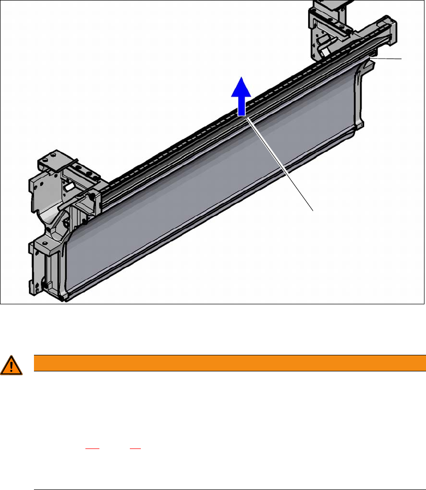
If feeder modules which use tapes with a pocket height of > 8 mm are used, remove the separating
plate (1).
4
(1) Separating plate for tapes > 8 mm, removable
(2) Fastening screws
4
Loosen the fastening screws.
Pull out the separating plate.
WARNING
Removing the dividing plate!
Switch the placement machine off at the main switch to remove the dividing plate.
Disconnect the placement machine from the power and compressed air supply.
Lock the placement machine to prevent unauthorized reactivation, as described in
section 2.9
, page 95.
Wait until the operating pressure for the tape cutter has dropped to 0 MPa.
Do not reach inside the empty tape duct.
(1)
(2)

4 Setting up and commissioning Instruction manual SIPLACE X-Series S
4.6 Commissioning the placement machine From software version 713.0 Edition 11/2019
226
4.6 Commissioning the placement machine
4.6.1 Commissioning the placement machine at the customer's premises
Check all modules for correct seating.
Remove the shipping braces (see section 4.3.9, page 4.3.9).
Wipe the linear guide rails of the X/Y axis with a lint-free cloth. Do not use any solvents (see
section 4.3.10
, page 222).
Connect the power and compressed air supplies. Make sure that the incoming leads and ca-
bles can not be tripped over. If possible, run the incoming cables under the placement ma-
chine.
Switch the placement machine on and check the function of the safety features such as the
EMERGENCY STOP button, position switch for covers and the component trolley.
Perform a reference run.
Perform initial calibration of the placement machine (see section 4.6.2.1, page 227).
Load a recipe in the computer and test it.
Check the placement machine zero point after a period of warming up of 3 - 4 h.
Get the customer's operating personnel to equip the feeder modules according to the cus-
tomer's placement program.
Instruct them in handling the feeder modules using the JobGuide.
4.6.2 Checking and setting the protective cover switch
Check the function of the protective cover switch (see 2.4.1 on page 63).
Adjust the protective cover switch if necessary (see service manual).
Instruction manual SIPLACE X-Series S 4 Setting up and commissioning
From software version 713.0 Edition 11/2019 4.6 Commissioning the placement machine
227
4.6.2.1 Performing initial calibration
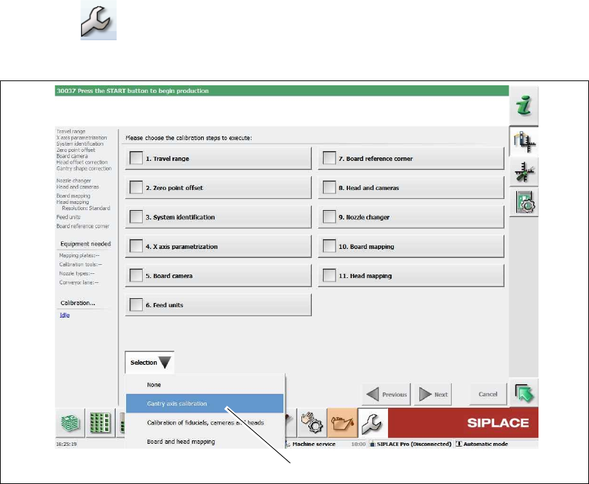
Click on "Service Tools" in the toolbar.
Click on the Automatic calibration button.
4
Fig. 4.6 - 1 Service tools => automatic calibration (example)
Select Selection => Gantry axis calibration (1).
(1)