00198711-01_UM_X-Serie-S_EN.pdf - 第176页
3 Technical data and assemblies Instruction manual SIPLACE X-Series 3.9 Component trolley From softwa re version 713.0 Edition 11/2019 176 3.9.5 Dimensions of SIPLACE X-Series S component trolley 3 Fig. 3.9 - 5 Dimension…
Instruction manual SIPLACE X-Series 3 Technical data and assemblies
From software version 713.0 Edition 11/2019 3.9 Component trolley
175
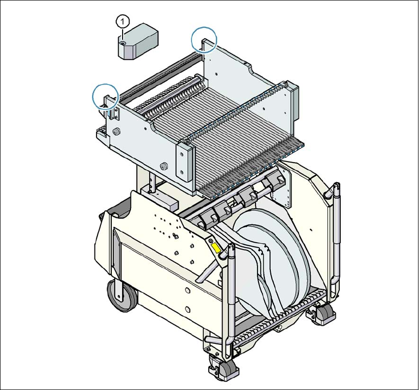
3.9.4 Fiducials on the SIPLACE X-Series S component trolley
3
Fig. 3.9 - 4 Fiducials on the SIPLACE X-Series S component trolley
(1) Fiducials on the component trolley
Once the SIPLACE X-Series S component trolley has been docked in, the placement machine
measures the
fiducials on the component trolley.
For components with an edge length of less than 0.5 mm, i.e. 0402 components and smaller, the
position of the component is determined with the tape pocket before the first component is picked
up.
3 Technical data and assemblies Instruction manual SIPLACE X-Series
3.9 Component trolley From software version 713.0 Edition 11/2019
176
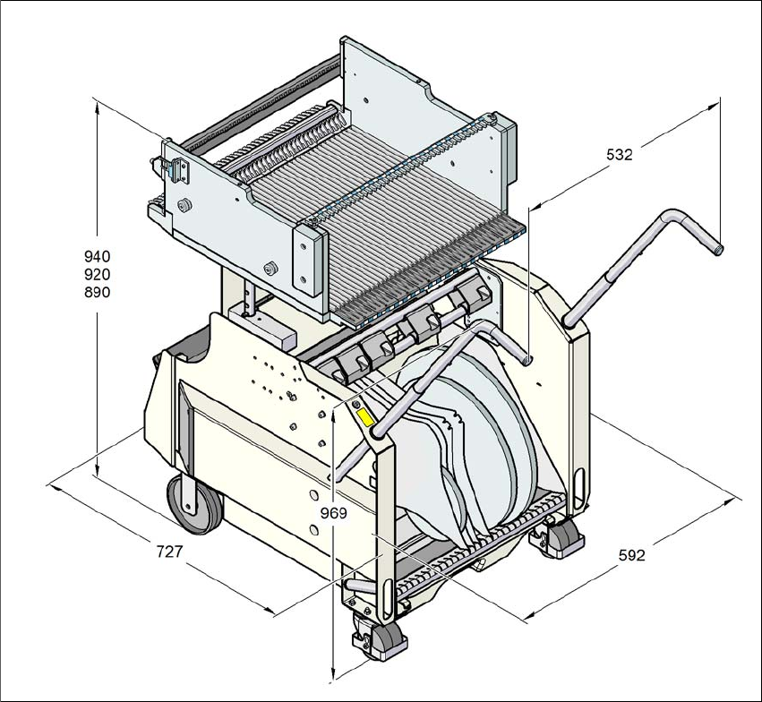
3.9.5 Dimensions of SIPLACE X-Series S component trolley
3
Fig. 3.9 - 5 Dimensions of the SIPLACE X-Series S component trolley; all dimensions in millimeters
Instruction manual SIPLACE X-Series 3 Technical data and assemblies
From software version 713.0 Edition 11/2019 3.9 Component trolley
177
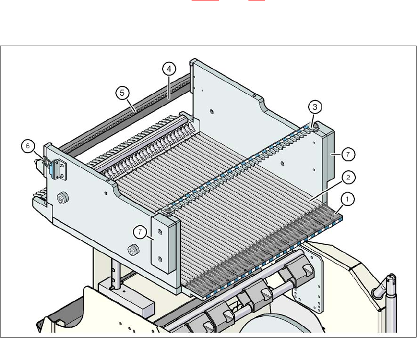
3.9.6 SIPLACE X-Series S changeover table
The front slider guides of the feeder modules are placed on the insertion aid. As it is pushed in,
the guides of the feeder module slide on the guide profile as far as the stop bar. A centering hole
on the stop bar holds the "front" centering pin of the X feeder module. At the same time, the
changeover table locking latch (item 1 in fig. 3.9 - 7
, page 178) engages onto the locking roller of
the feeder module. The "back" centering pin on the top of the feeder module is held by the recess
in the centering bar.
3
Fig. 3.9 - 6 Changeover table, SIPLACE X-Series S, rear view
(1) Insertion aid
(2) Guide profile (Ω profile)
(3) Centering bar for holding the "back" centering pin for X feeder modules
(4) Stop bar
(5) Centering holes
(6) Contact for switching the safety switch of the EMERGENCY STOP circuit
(7) Hand guard