00198711-01_UM_X-Serie-S_EN.pdf - 第153页
Instruction manual SIPLACE X-Series 3 Technical data and assemblies From software version 713.0 Edition 11/2019 3.8 SIPLACE ta pe feeder modules for SIPLACE X-Series S 153 3.8.1.3 Design of the SIPLACE SmartFeeder X The …

3 Technical data and assemblies Instruction manual SIPLACE X-Series
3.8 SIPLACE tape feeder modules for SIPLACE X-Series S From software version 713.0 Edition 11/2019
152
3.8 SIPLACE tape feeder modules for SIPLACE X-Series S
The SIPLACE X-Series S uses the SIPLACE SmartFeeder X and the SIPLACE SmartFeeder Xi.
The specified tape feeder modules are compatible with the SIPLACE X-Series S changeover ta-
bles. Key features of the SIPLACE tape feeder modules include high pickup position precision,
online programming and simple handling of feeder module changeovers during the placement
process. The power supply to the feeder modules is contactless and uses an inductive interface.
Each feeder module communicates with the feeder module control unit (FCU) via two optoelec-
tronic channels (optical fiber). The two interfaces form the EDIF assembly (energy and data inter-
face).
3.8.1 SIPLACE tape feeder module
3.8.1.1 Tape material
The possible tape widths range from 4 mm to 104 mm. The tape material is blister or paper. Com-
ponent tapes with a permanently adhesive cover foil (PSA foil) can also be processed.
The design of the tape feeder modules was based on the following tape standards:
DIN EN 60286-3 (12/1998) / IEC 60286-3 (12/1997)
JIS C 0806-3 (1999)
ANSI/EIA 481-C (10/2003)
IEC 60286-3-2 3
3.8.1.2 Manual removal of tantalum capacitors which were not picked up
To prevent tantalum capacitors which were not picked up from causing the tape material to burn
when it is cut, the user interface has been extended to include the option "Stop immediately on
pickup error". This option must be enabled in SIPLACE Pro. On the placement machine, the com-
ponent that was not picked up is paced forward again until it is ready for removal from the com-
ponent tape. The track is deactivated and the operator is sent an error message to remind him to
pick up the tantalum component from the tape. If an alternative track is available, the placement
machine continues placing. The operator is able to stop the placement machine, however, and re-
move the tantalum component. If no alternative track is available and it is not possible to continue
placement with other components, the placement machine will stop. At this point, the operator can
again remove the tantalum component and acknowledge the error. Once the operator has re-
started the placement machine, placement is continued and components are picked up from the
track that is now enabled once more.
3
PLEASE NOTE
This software function is also a good idea for expensive components.
Please observe the safety instructions for capacitors on metallic powder basis (see
section 2.5.3
, page 68).
Instruction manual SIPLACE X-Series 3 Technical data and assemblies
From software version 713.0 Edition 11/2019 3.8 SIPLACE tape feeder modules for SIPLACE X-Series S
153
3.8.1.3 Design of the SIPLACE SmartFeeder X
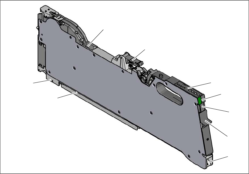
The following diagram shows the design of the SIPLACE SmartFeeder X.
3
Fig. 3.8 - 1 SIPLACE SmartFeeder X
(1) Entry to the tape guide channel with tape spring
(2) Flap on cover foil container
(3) Removal handle, engaged
(4) Status display
(5) Operating panel - LED display
(6) Foil rocker
(7) Tape guide channel outlet
(8) Front slider guide
(9) Back slider guide
(1)
(2)
(3)
(4)
(5)
(6)
(8)
(9)
(7)
3 Technical data and assemblies Instruction manual SIPLACE X-Series
3.8 SIPLACE tape feeder modules for SIPLACE X-Series S From software version 713.0 Edition 11/2019
154
3.8.1.4 Design of the SIPLACE SmartFeeder Xi
3
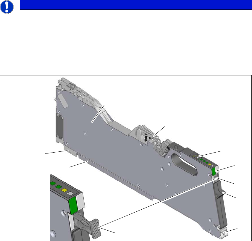
The following diagram shows the design of the SIPLACE SmartFeeder Xi, using the example of
the SIPLACE SmartFeeder 2 x 8 mm Xi. The SIPLACE SmartFeeder Xi can be recognized by its
slanted and grooved surface on the removal handle.
3
Fig. 3.8 - 2 SIPLACE SmartFeeder 2 x 8 mm Xi
(1) Entry to the tape guide channel with tape spring
(2) Flap on cover foil container
(3) Removal handle, docked (grooved surface)
(4) Status display
(5) Operating panel - LED display
(6) Foil rocker
(7) Tape guide channel outlet
(8) Front slider guide
(9) Back slider guide
PLEASE NOTE
Maximum speed with SIPLACE SmartFeeder Xi.
The SpeedStar C&P20 P20 P / P2 can only reach maximum speed in conjunction with
the SIPLACE SmartFeeder Xi.
(1)
(2)
(3)
(4)
(5)
(6)
(8)
(9)
(7)
(3)