00198711-01_UM_X-Serie-S_EN.pdf - 第83页
Instruction manual SIPLACE X-Series S 2 Operational safety From software version 713.0 Edition 11/2019 2.6 Safety features 83 Stop button, black (item 2 in fig. 2.6 - 5 , page 79 in fig. 2.6 - 6 , page 80 ) 2 These butto…
2 Operational safety Instruction manual SIPLACE X-Series S
2.6 Safety features From software version 713.0 Edition 11/2019
82
2.6.3.3 Description of functions
Main switch in OFF position (see item 1 in fig.
2.6 - 5, page 79) 2
The main power switch disconnects the three phases L1, L2, and L3 from the power supply.
2
2
Main switch in ON position 2
When the main switch is switched to ON, the mains voltage is switched through and all AC/DC
converters are addressed.
The control computer will start and all supply voltages will be made available internally. The inter-
mediate circuit voltages for the gantry axes (300 V-) and star axes (160 V-) plus the supply voltage
for the conveyor drives are also connected via the start button for safety purposes.
Start button, white (item 1 in fig. 2.6 - 5, page 79 and in fig. 2.6 - 6, page 80) 2
After switching on the main power switch you will be prompted to press the start button in order to
start the placement machine for placement jobs. The same prompt appears if you open the pro-
tective covers or the press the EMERGENCY STOP button.
Press the start button for at least 200 ms, up to a maximum of 1500 ms, and then let go. The
placement machine is switched on when you let go of the button.
DANGER
Incorrect handling of this placement machine can therefore result in death or severe in-
jury or considerable damage to equipment.
The following components still carry potentially lethal voltages even if the main power
switch is switched off:
– Cable connection terminals L1, L2, and L3 of the S1 main power switch
– Main input terminal X94
– The color of all individual wires, which still carry electricity, even if the main power
switch is switched off, is orange.
Always follow the applicable accident prevention and DIN regulations (particularly
EN 60204, part 1 or IEC 60204, part 1) and the applicable regulations in your own
country.
The safety door to the power supply must ONLY be opened by appropriately quali-
fied and trained personnel.
DANGER
Due to the use of energy storage devices in the power supply unit, hazardous voltages
are still present in parts of the power supply unit for approx. 5 minutes after turning off
the main switch and disconnecting from the mains power supply.
Instruction manual SIPLACE X-Series S 2 Operational safety
From software version 713.0 Edition 11/2019 2.6 Safety features
83
Stop button, black (item 2 in fig. 2.6 - 5, page 79 in fig. 2.6 - 6, page 80) 2
These buttons are used to stop the placement machine.
Component counter 2
The number of placed components (component counter) can be read on the station software. For
more information, refer to the Online Help.
EMERGENCY STOP button with forced locking (item 3 in fig. 2.6 - 5, page 79 and in fig. 2.6 - 6,
page
80) 2
The EMERGENCY STOP button is red and latches in the ON position when pressed. When you
press the EMERGENCY STOP button, the switching contact of the EMERGENCY STOP circuit
opens and the safety cutoff (CBS) trips. The intermediate circuit voltage (300 V-) for the gantry
axes and the intermediate circuit voltage (160 V-) for the star axes plus the drive voltage for the
PCB conveyor are switched off. The servo amplifiers for the DP and Z axes are still supplied with
42 V- and therefore held in position. The signaling contact of the EMERGENCY STOP button
opens and the message "EMERGENCY STOP pressed" appears on the screen. The following
modules are deactivated:
– PCB conveyor
– PCB clamping
– Width adjustment
– PCB stopper
– Compressed air supply for empty tape cutter
2
Protective cover switch 1 to 4 (items 1 to 4 in fig. 2.6 - 7, page 81) 2
These switches check whether the protective covers are closed. When they are closed, the
EMERGENCY STOP contact, the signaling contact and also the EMERGENCY STOP circuit are
closed. If one of the covers is opened, the EMERGENCY STOP contact and the signaling contact
will open. Individual components are disabled or remain enabled (see fig. 2.6 - 9
, page 86 ).
Protective cover switch for service flap (optional) 2
This switch checks whether the service flap is closed. When they are closed, the EMERGENCY
STOP contact and the signaling contact are closed. If the service flap is opened, the EMER-
GENCY STOP contact and the signaling contact will open. Individual components are disabled or
remain enabled (see fig. 2.6 - 9
, page 86 ).
PLEASE NOTE
Placement will be interrupted and can then either be continued or canceled once the
placement machine is working correctly again.
2 Operational safety Instruction manual SIPLACE X-Series S
2.6 Safety features From software version 713.0 Edition 11/2019
84
2.6.4 Safety cutoff (CSB)
2
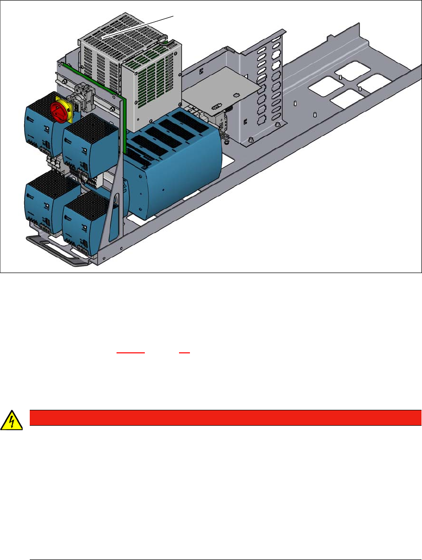
Fig. 2.6 - 8 Position of the safety cutoff (CSB)
2
(1) Safety cutoff (CSB)
Safety cutoff (CSB) (item 1 in fig. 2.6 - 8, page 84) 2
The safety cutoff (CSB) is located in the power supply unit. It is used to monitor the protective fea-
tures and checks for hazardous voltages or movements.
2
(1)
DANGER
Lethal voltages under the safety cutoff (CSB) cover!
Under the cover there are components which could still carry lethal voltages, even when
the placement machine is switched off and the mains plug has been disconnected. After
disconnecting the mains plug, wait approx. 5 minutes until the capacitors have dis-
charged.
Never open the covers.
Only ASM Assembly Systems GmbH&Co.KG service engineers or the machine
owner's service engineers, who have been trained by ASM, may perform work on the
power supply and the safety cutoff (CBS).