00198711-01_UM_X-Serie-S_EN.pdf - 第116页
3 Technical data and assemblies Instruction manual SIPLACE X-Series 3.5 Placement head From software version 713.0 Edition 11/2019 116 3.5 Placement head 3.5.1 SIPLACE SpeedSt ar C&P20 P for very hig h speed placemen…
Instruction manual SIPLACE X-Series 3 Technical data and assemblies
From software version 713.0 Edition 11/2019 3.4 Overview of the modules
115
3.4 Overview of the modules
3
3
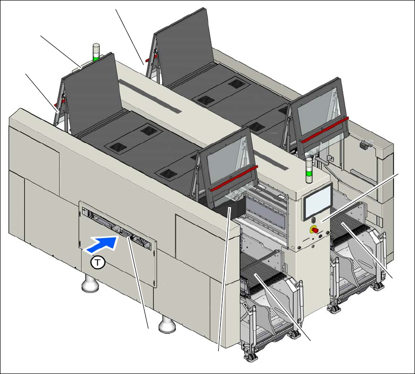
Fig. 3.4 - 1 Overview of assemblies - example of X3 S shown
(1) Location 1 with component trolley, tape cutter, empty tape duct
(2) Location 2 with component trolley, tape cutter, empty tape duct
(3) Location 3 with COT insert, tape cutter, empty tape duct
(4) Location 4 with COT insert, tape cutter, empty tape duct
(5) Gantry 1 at location 1 with placement head
(6) Multitouch monitor
(7) Board conveyor
(T) Direction of PCB transport
(1)
(2)
(3)
(4)
(6)
(7)
(7)
(5)

3 Technical data and assemblies Instruction manual SIPLACE X-Series
3.5 Placement head From software version 713.0 Edition 11/2019
116
3.5 Placement head
3.5.1 SIPLACE SpeedStar C&P20 P for very high speed placement
The SIPLACE X-Series S uses the SIPLACE SpeedStar C&P20 P for top placement performance.
3
CAUTION
Always take hold of the handle to push the placement head
The placement head may only be moved by pushing manually against the handle provid-
ed.
Instruction manual SIPLACE X-Series 3 Technical data and assemblies
From software version 713.0 Edition 11/2019 3.5 Placement head
117
3.5.1.1 Overview
3
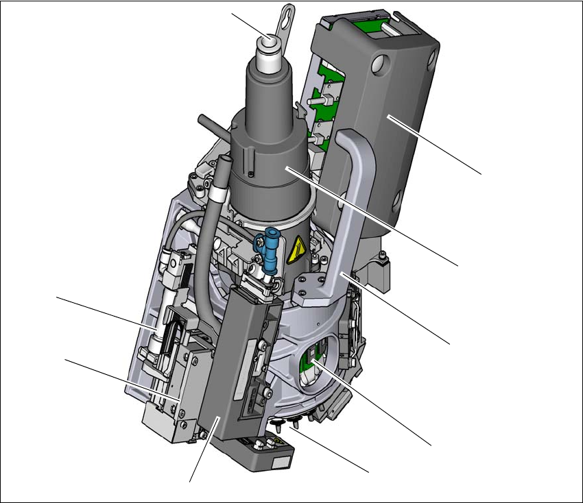
Fig. 3.5 - 1 SIPLACE C&P20 P - overview
(1) Compressed air connection for 20 Venturi nozzles in the pickup/placement and holding circuit
(2) "Vacuum sensor hold circuit" board
(3) Star motor
(4) Handle
(5) DP drive, 20 drives
(6) Star with 20 nozzles
(7) Pressure control valve
(8) Z motor (linear motor)
(9) Return cylinder
(5)
(1)
(7)
(2)
(3)
(4)
(6)
(8)
(9)