00198711-01_UM_X-Serie-S_EN.pdf - 第169页
Instruction manual SIPLACE X-Series 3 Technical data and assemblies From software version 713.0 Edition 11/2019 3.8 SIPLACE ta pe feeder modules for SIPLACE X-Series S 169 3 3 Fig. 3.8 - 1 1 Using a waffle pack tray hold…
3 Technical data and assemblies Instruction manual SIPLACE X-Series
3.8 SIPLACE tape feeder modules for SIPLACE X-Series S From software version 713.0 Edition 11/2019
168
3.8.7.1 Technical data
3
3.8.7.2 Number of waffle pack trays per location and placement machine
3.8.7.3 Inserting a tray holder on the X-Series S component trolley
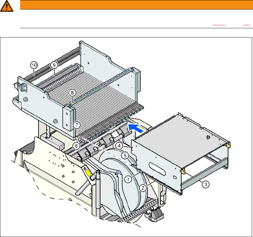
Place the two front slider guides (item 1 in fig. 3.8 - 11, page 169) for the holder onto the in-
sertion aid (item 6 in fig. 3.8 - 11, page 169 ).
Push the holder along the guide profiles (item 7 in fig. 3.8 - 11, page 169), towards the front.
The holder slides with the front (item 1) and back slide guides (item 2 in fig. 3.8 - 11, page
169) on the guide profiles.
Continue pushing the holder, until the two centering pins "front" (item 4 in fig. 3.8 - 11, page
169) disappear into the centering holes (item 10 in fig. 3.8 - 11, page 169).
Check the two "back" centering pins (item 3 in fig. 3.8 - 11, page 169) for the holder. They
should slide easily into the recesses (item 8 in fig. 3.8 - 11, page 169) of the centering rail.
At the end stop of the holder, the locking latches (item 9 in fig. 3.8 - 11, page 169) engage
with the locking rollers (item 5) of the holder.
The waffle pack tray holder can be locked and released via the user interface. You can therefore
easily change the holder without interruption to machine operation.
Dimensions L x W x H 429 mm x 376 mm x 200 mm
Location occupied on the changeover table 32 locations
*a
*)a X feeder modules can be placed on the remaining 8 locations. When using locking bars/mounting rails, the
locations available are reduced to 6, due to the fixation lever which protrudes at the side.
Positioning options on X-Series S placement ma-
chines
Locations 2 and/or 4
Placement head range TwinStar, CPP
*b
*)b Only permitted in high assembly position (CPP_H).
PLEASE NOTE
Further information
The maximum component height for the waffle pack tray holder depends on the maxi-
mum component height for the placement head used. When using waffle pack trays,
bear in mind that the components may not higher than the pickup height of a standard
feeder.
Placement machine Location 2 Location 4
X4 S 1 1
X3 S 2 1
X2 S 2 2
Instruction manual SIPLACE X-Series 3 Technical data and assemblies
From software version 713.0 Edition 11/2019 3.8 SIPLACE tape feeder modules for SIPLACE X-Series S
169
3
3
Fig. 3.8 - 11 Using a waffle pack tray holder on the X-Series S component trolley
WARNING
Occupation of locations!
Always follow the safety instructions about occupying locations, in section 2.6.5
, page 88.
(1) Front slider guide (6) Insertion aid
(2) Back slider guide (7) Sliding rail (omega profile)
(3) "Back" centering pin (8) Recesses in the centering bar for holding the
"back" centering pin
(4) "Front" centering pin (9) Locking latches
(5) Locking roller (10) Centering holes on the changeover table for
holding the "front" centering pin
3 Technical data and assemblies Instruction manual SIPLACE X-Series
3.9 Component trolley From software version 713.0 Edition 11/2019
170
3.9 Component trolley
Item no. 00119722-xx SIPLACE X-Series S component trolley
Four SIPLACE X-Series S component trolleys can be docked onto SIPLACE X-Series S place-
ment machines.
3
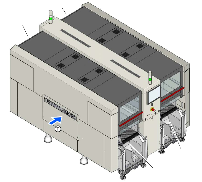
Fig. 3.9 - 1 Component trolley locations (example of SIPLACE X4i S shown)
(1) Location 1
(2) Location 2
(3) Location 3
(4) Location 4
(T) Direction of PCB transport
The component trolleys are stand-alone modules that can be set up with feeders at an external
setup area. This means that the production process only has to be interrupted briefly in order to
change the component trolley.
(1)
(4)
(2)
(3)