00198711-01_UM_X-Serie-S_EN.pdf - 第280页
5 Tasks at the placement machine Ins truction manual SIPLACE X-Series S 5.14 Docking the component trolley in or out From software version 713.0 Edition 11/2019 280 5.14 Docking the component trolley in or out 5.14.1 Saf…
Instruction manual SIPLACE X-Series S 5 Tasks at the placement machine
From software version 713.0 Edition 11/2019 5.13 Avoiding track errors
279
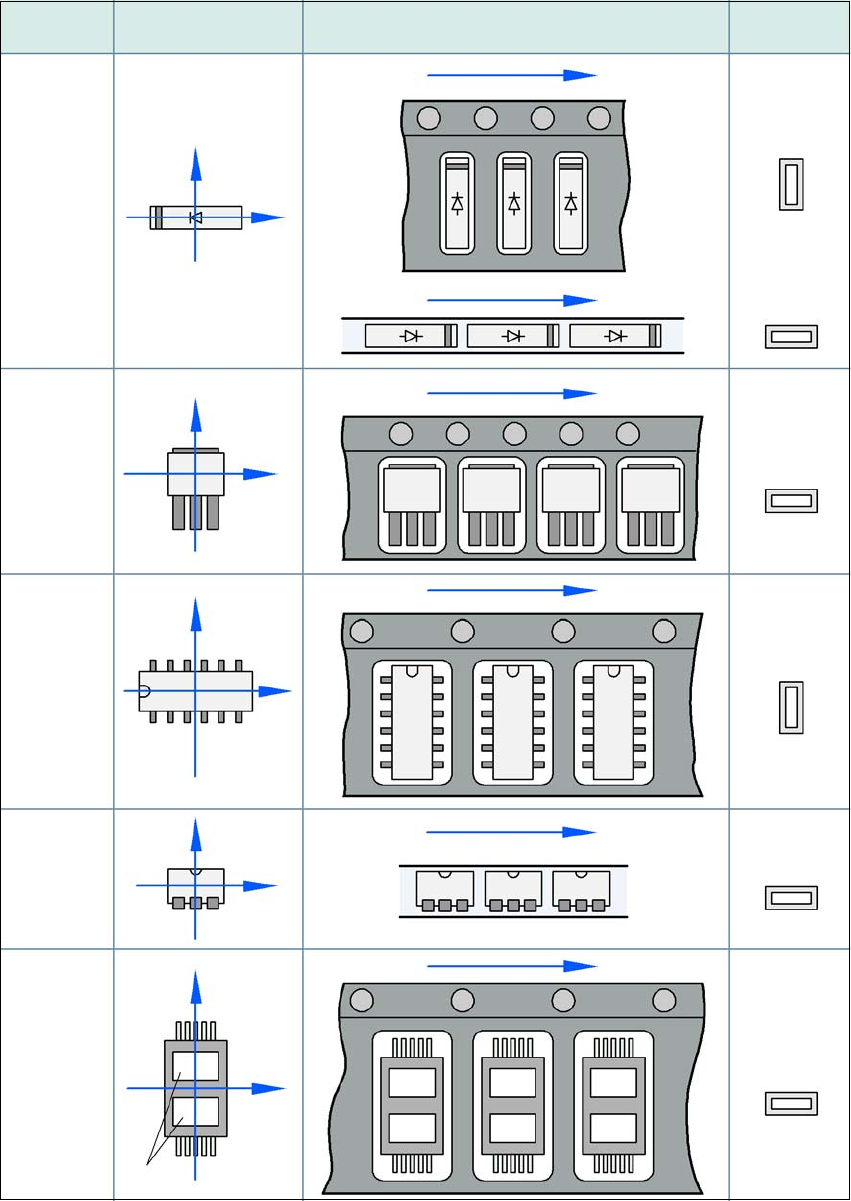
5.13.3 Component coordinate system and pickup angle
5
Fig. 5.13 - 1 Position of the component and its pick-up angle
Special
component
Stick
magazine:
Chip-
components
with polarity
0402
2220
The anode must be
aligned with the +X
coordinate.
Package form 0° coordinate system
Position in the feeder module
Pickup angle/
nozzle angle
Tape:
SOT 23
Stick
magazine:
Tape:
Tape:
SO-IC
DIL-IC
SOT 194
Tape:
Holes
Y
X
Y
X
Y
X
Y
X
Y
X
90°
90°
0°
90°
-90°
0°
5 Tasks at the placement machine Instruction manual SIPLACE X-Series S
5.14 Docking the component trolley in or out From software version 713.0 Edition 11/2019
280
5.14 Docking the component trolley in or out
5.14.1 Safety instructions for docking component trolleys in and out
Also follow the safety instructions given in section 2.5.10, page 73.
5
In addition, the component trolley can only be docked in if the protective
covers are closed.
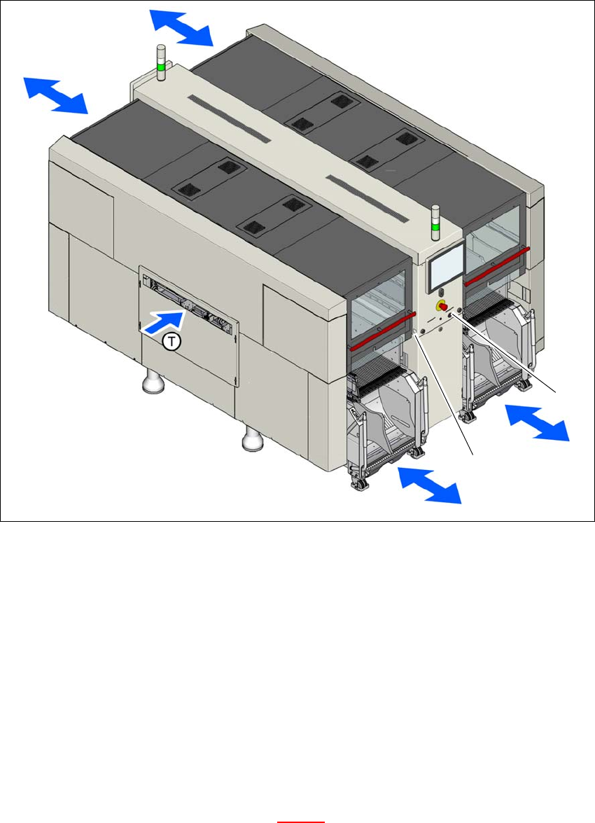
There is a button at each location (1,2,3 and 4) for docking and undocking the component trolley.
The safety concept for the component trolley changeover specifies that the operator should push
this button at the relevant placement machine location, to dock or undock the component trolley.
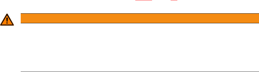
WARNING
DANGER OF CRUSHING!
Risk of crushing when docking and undocking the component trolley.
Always dock/undock the component trolley alone.
When docking and undocking, make sure that there are no body limbs in the travel
area of the component trolley.
Instruction manual SIPLACE X-Series S 5 Tasks at the placement machine
From software version 713.0 Edition 11/2019 5.14 Docking the component trolley in or out
281
5
Fig. 5.14 - 1 Safety instructions for docking the component trolley in or out (example of SIPLACE X2 S / X3 S / X4 S
shown)
In addition, the component trolley can only be docked in if the protective
covers are closed.
(1) Button for docking and undocking the component trolley at location 1
(2) Button for docking and undocking the component trolley at location 2
(T) Direction of PCB transport
5.14.2 Docking out the component trolley
Press the docking/undocking button on the respective placement machine location until the
component trolley is completely undocked.
Swivel the two handles up (item 1 in fig. 5.14 - 2).
(1)
(2)