00198711-01_UM_X-Serie-S_EN.pdf - 第194页
4 Setting up and commissioning Instruct ion manual SIPLACE X-Series S 4.2 Infrastructure at the installation location From software versio n 713.0 Edition 11/2019 194 4.2.3 Main power supply 4 Fig. 4.2 - 3 Position of po…
Instruction manual SIPLACE X-Series S 4 Setting up and commissioning
From software version 713.0 Edition 11/2019 4.2 Infrastructure at the installation location
193
4.2.2.2 Compressed air connection on the placement machine
4
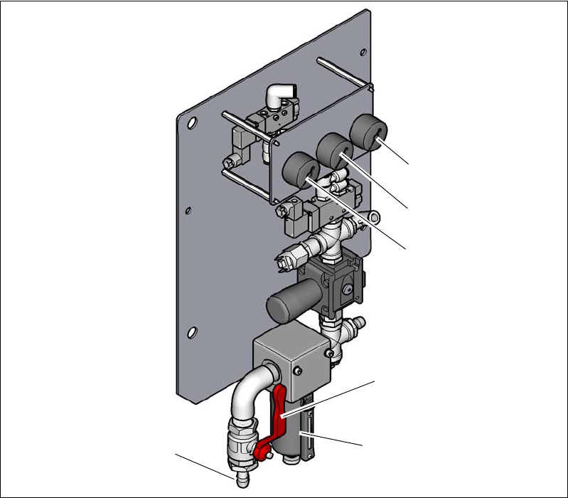
Fig. 4.2 - 2 Compressed air unit on the placement machine
Legend for fig.4.2 - 2
(1) Manometer for the machine component supply pressure
Target pressure: 0.5 ± 0.025 MPa, 5 ± 0.25 bar (display range 0 - 1.0 MPa, 0 - 10 bar)
(2) Manometer for supply pressure of gantries 1 to 4
Target pressure: 0.46 ± 0.01 MPa, 4.6 ± 0.1 bar (display range 0 - 1.0 MPa, 0 - 10 bar)
(3) Manometer for inlet pressure
Target pressure: 0.5 - 1.0 MPa, 5 - 10 bar (display range: 0 - 1.0 MPa, 0 - 10 bar)
(4) Stop valve in the "OPEN" position
(5) Compressed air filter
(6) Compressed air connection
(6)
(1)
(2)
(3)
(5)
(4)
4 Setting up and commissioning Instruction manual SIPLACE X-Series S
4.2 Infrastructure at the installation location From software version 713.0 Edition 11/2019
194
4.2.3 Main power supply
4
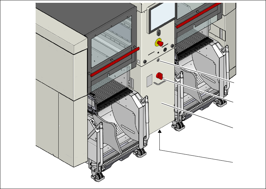
Fig. 4.2 - 3 Position of power supply on the placement machine (example of SIPLACE X2 S / X3 S / X4 S shown)
(1) Lock
(2) Main power switch secured to prevent switching on again
(3) Power supply unit (behind the cover)
(4) Main connection cable from below to the power supply
(1)
(2)
(3)
(4)
Instruction manual SIPLACE X-Series S 4 Setting up and commissioning
From software version 713.0 Edition 11/2019 4.2 Infrastructure at the installation location
195
4.2.3.1 Danger notes
4
4
4.2.3.2 Checking the main power supply
Check whether the power supply complies with the prescribed machine specifications (see table
in section 3.2.4
, page 109).
4
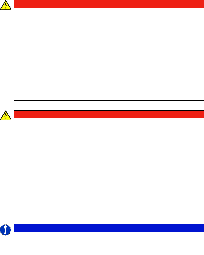
DANGER
Dangerous voltage levels!
The placement machine is supplied with 3 x 380 V~ to 3 x 415 V ± 10 %, 50/60 Hz or op-
tionally with
3 x 200 V~ to 3 x 220 V~ ± 10 %; 50/60 Hz mains voltage. This means that some parts of
the system carry potentially lethal voltages - even when switched off at the main power
switch and with disconnected mains plug.
Incorrect handling of this placement machine can therefore result in death or severe injury
or considerable damage to equipment.
Always follow the applicable accident prevention and DIN regulations (particularly EN
60204, part 1 or IEC 60204, part 1) and the applicable regulations in your own coun-
try.
The covers over the power supply unit may ONLY be opened by appropriately quali-
fied and trained personnel.
DANGER
Lethal voltages under the safety cutoff (CSB) cover!
Under the cover there are components which could still carry lethal voltages for a certain
time, even when the placement machine is switched off and the mains plug has been dis-
connected. After disconnecting the mains plug, wait 5 minutes until the capacitors have
discharged.
Never open the covers.
Only ASM Assembly Systems GmbH&Co.KG service engineers or the machine
owner's service engineers, who have been trained by ASM, may perform work on the
power supply and the safety cutoff (CBS).
PLEASE NOTE
Load peaks in power supply
For technical reasons, load peaks occur in the power supply.
Please contact your power company to clarify the mains impedance, if necessary.