00198711-01_UM_X-Serie-S_EN.pdf - 第337页
Instruction manual SIPLACE X-Series S 6 Station extensions From software version 713.0 Edition 11/2019 6.11 Support pin 337 6.1 1 Support pin Item no. 001 19680-xx Support pin Wide boards tend to deflect dur ing placemen…
6 Station extensions Instruction manual SIPLACE X-Series S
6.10 IPC-Hermes-9852 From software version 713.0 Edition 11/2019
336
6.9.2.1 Safety instructions
6
6.9.2.2 Technical data
6
6
6.10 IPC-Hermes-9852
IPC-HERMES-9852 is a communication protocol for SMT lines and can replace the IPC SMEMA
interface. This protocol allows you to transfer more information than previously via the IPC
SMEMA interface.
This could be, for example:
– Unique board IDs
– Barcodes
– Conveyor speed,
– Board length and width
– Board thickness
– Transport clearance height
All this information can be transmitted along the whole line without interruption.
For a detailed description, see the Administrator Manual IPC-HERMES-9852, item no.
[00198615-xx].
WARNING
Risk of collisions!
When changing the placement head from a TwinStar/VHF to a SpeedStar, the SpeedStar
collides with the camera housing.
Dismantle the stationary component camera for the TwinStar.
When changing the placement head from a TwinStar to a SIPLACE MultiStar CPP,
the stationary component camera is fitted in the bottom position.
Component dimensions 0.5 mm x 0.5 mm to 55 mm x 45 mm
Component range 0402, MELF, SO, PLCC, QFP, electrolytic capacitors, BGA
Min. lead pitch 0.3 mm
Min. lead width 0.15 mm
Min. ball pitch 0.35 mm
Min. ball diameter 0.2 mm
Field of vision 65 mm x 50 mm
Illumination type Front-illumination (6 levels, programmable as required)
Instruction manual SIPLACE X-Series S 6 Station extensions
From software version 713.0 Edition 11/2019 6.11 Support pin
337
6.11 Support pin
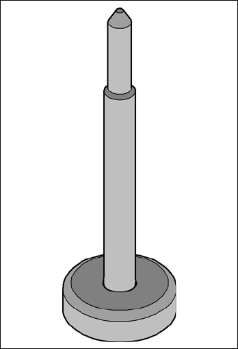
Item no. 00119680-xx Support pin
Wide boards tend to deflect during placement such that, under certain circumstances, the compo-
nents can no longer be placed with the desired accuracy. Highly curved PCBs also affect the
placement accuracy. This problem can be easily rectified by fitting support pins on the lifting table.
6
Fig. 6.11 - 1 Support pin
6 Station extensions Instruction manual SIPLACE X-Series S
6.12 Smart Pin Support From software version 713.0 Edition 11/2019
338
6.12 Smart Pin Support
Item no. 00119999-xx Smart Pin Support, X3 S
Item no. 00119993-xx Smart Pin Support, X4 S
Item no. 00119994-xx Smart Pin Support, X4i S
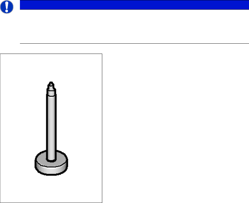
Wide boards tend to deflect during placement such that, under certain circumstances, the compo-
nents can no longer be placed with the desired accuracy. Highly curved PCBs also affect the
placement accuracy. This problem can be easily rectified by fitting support pins on the lifting table.
The support pins are automatically placed on the lifting table with the help of the Smart Pin Sup-
port option. A gripper unit is used to pick the support pins up from special magazines and place
them in the prescribed positions.
6
Fig. 6.12 - 1 Support pin
PLEASE NOTE
Reducing the hazard area
The Smart Pin Support option can be configured for SIPLACE X3 S / X4 S placement
machines. The Smart Pin Support option reduces the travel range of gantry 1 and 3 in
both placement areas by 36 mm in each case.