00198711-01_UM_X-Serie-S_EN.pdf - 第80页
2 Operational safety Instruction manual SIPLACE X-Series S 2.6 Safety features From software version 713.0 Edition 11/2019 80 2 Fig. 2.6 - 6 Position of buttons and switches - view of PC B input side (example of SIPLACE …
Instruction manual SIPLACE X-Series S 2 Operational safety
From software version 713.0 Edition 11/2019 2.6 Safety features
79
2.6.3 Switches and buttons on the placement machine
2.6.3.1 Position of switches and buttons on the placement machine
2
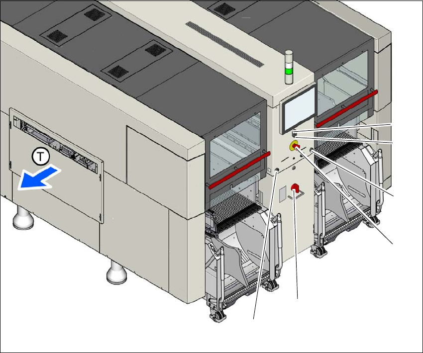
Fig. 2.6 - 5 Position of buttons and switches - view of PCB output side (example of SIPLACE X2 S / X3 S / X4 S
shown)
(1) Start button (white)
(2) Stop button (black)
(3) EMERGENCY STOP button
(4) Main switch
(5) Button for docking and undocking the component trolley at the respective location
(T) PCB transport direction
(3)
(1)
(4)
(2)
(5)
(5)
2 Operational safety Instruction manual SIPLACE X-Series S
2.6 Safety features From software version 713.0 Edition 11/2019
80
2
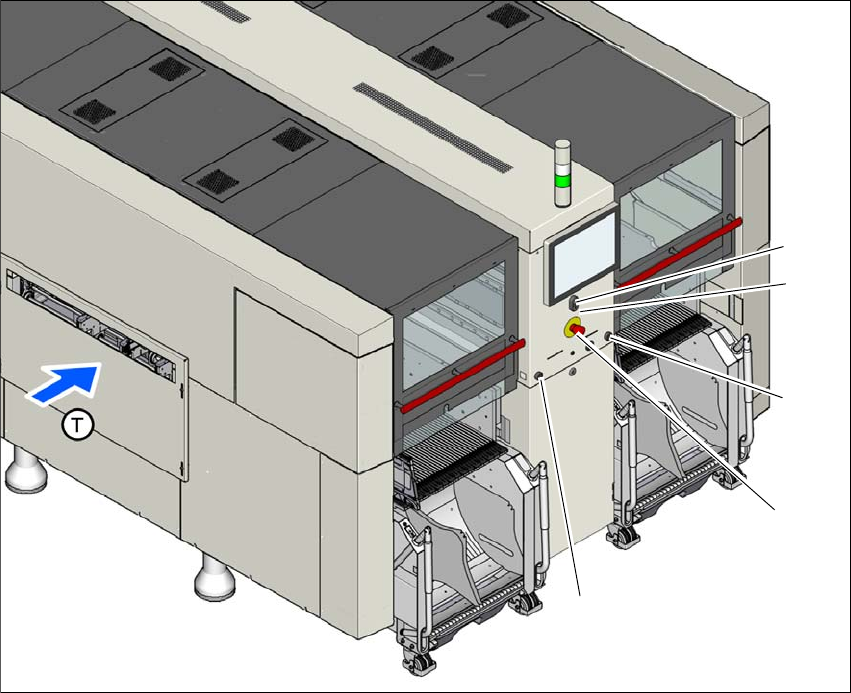
Fig. 2.6 - 6 Position of buttons and switches - view of PCB input side (example of SIPLACE X2 S / X3 S / X4 S
shown)
(1) Start button (white)
(2) Stop button (black)
(3) EMERGENCY STOP button
(4) Button for docking and undocking the component trolley at the respective location
(T) PCB transport direction
(3)
(1)
(4)
(2)
(4)
Instruction manual SIPLACE X-Series S 2 Operational safety
From software version 713.0 Edition 11/2019 2.6 Safety features
81
2.6.3.2 Position of protective switches on the placement machine
2
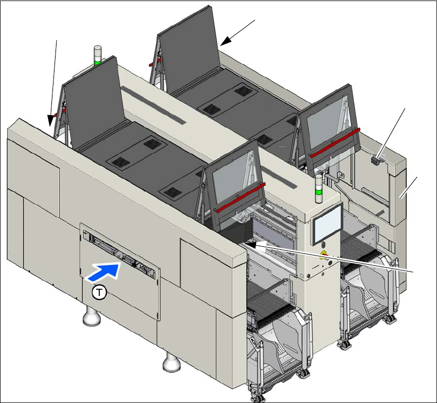
Fig. 2.6 - 7 Position of protective switches on the placement machine (example of SIPLACE X4i S shown)
(1) Protective cover switch, location 1
(2) Protective cover switch, location 2
(3) Protective cover switch, location 3
(4) Protective cover switch, location 4
(5) Example service flap with protective cover switch at location 2 (optional at all locations)
(T) PCB transport direction
(2)
(3)
(1)
(4)
(5)