00198711-01_UM_X-Serie-S_EN.pdf - 第163页
Instruction manual SIPLACE X-Series 3 Technical data and assemblies From software version 713.0 Edition 11/2019 3.8 SIPLACE ta pe feeder modules for SIPLACE X-Series S 163 3.8.5 Energy and dat a interface (EDIF) for X fe…
3 Technical data and assemblies Instruction manual SIPLACE X-Series
3.8 SIPLACE tape feeder modules for SIPLACE X-Series S From software version 713.0 Edition 11/2019
162
3.8.4.3 Feeder module adapter with reject conveyor (reject module)
3
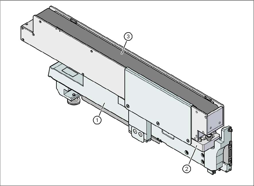
Fig. 3.8 - 7 Feeder module adapter with reject conveyor
(1) Adapter for feeder modules (item no. 00141305-xx)
(2) Adapter plate for reject conveyor (item no. 00141308-xx)
(3) Reject conveyor (reject module)
Instruction manual SIPLACE X-Series 3 Technical data and assemblies
From software version 713.0 Edition 11/2019 3.8 SIPLACE tape feeder modules for SIPLACE X-Series S
163
3.8.5 Energy and data interface (EDIF) for X feeder modules
Item no. 00141247-xx Energy and data interface for X feeder modules
3
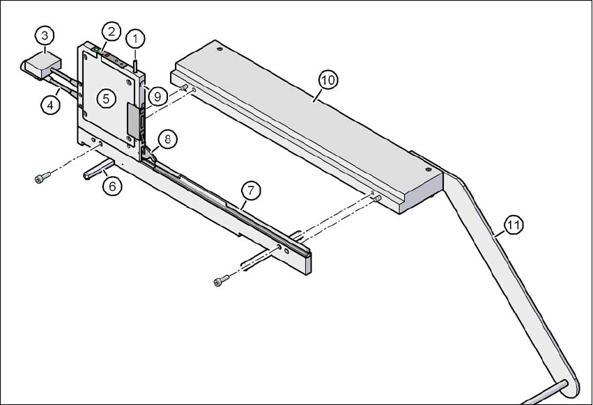
Fig. 3.8 - 8 Energy and data interface for X feeder modules
(1) Unlocking button for locking latch
(2) Operator panel
(3) Data cable
(4) Power supply cable
(5) Electronics housing
(6) Fold-out feet
(7) Omega profile for guiding feeder modules
(8) Locking latch
(9) Locating hole for front centering pin of feeder module
(10) Base plate
(11) Tape reel holder

3 Technical data and assemblies Instruction manual SIPLACE X-Series
3.8 SIPLACE tape feeder modules for SIPLACE X-Series S From software version 713.0 Edition 11/2019
164
3.8.5.1 Description
The energy and data interface allows X feeder modules to be used outside the placement machine
and presetup area. The interface consists of an aluminum frame with omega profile (item 7 in fig.
3.8 - 6
, page 161) for holding and guiding the feeder modules. As with the X component trolley,
the feeder module is placed on the omega profile, with the slider guides, and is pushed forwards
until the front centering pin of the feeder module is fully inserted into the locating hole (item 9 in
fig. 3.8 - 6
, page 161). The locking latch (item 8 in fig. 3.8 - 6, page 161) locks the feeder module
in this position. To remove the feeder module, simply press the release button (item 1 in fig.
3.8 - 6
, page 161 ). The locking latch (item 8 in fig. 3.8 - 6, page 161) is pressed down and releases
the feeder module. Fold-out feet (item 6 in fig. 3.8 - 6
, page 161) stabilize the position of the energy
and data interface, particularly for wide feeder modules.
The electronic housing (item 5 in fig. 3.8 - 6
, page 161) holds the electronic control unit for the
energy and data interface. The operator panel (item 2 in fig. 3.8 - 6
, page 161) consists of start
and stop buttons and two status LEDs. Communication with a PC takes place via the data cable
(item 3 in fig. 3.8 - 6
, page 161 ). The power supply cable (item 4 in fig. 3.8 - 6, page 161) is con-
nected to the power supply unit provided.
3.8.5.2 Usage
The energy and data interface is used to check, maintain and repair X feeder modules. It can also
be used for setting up in advance for PCB production. In this case, the energy and data interface
is fixed to the base plate (item 10 in fig. 3.8 - 8
, page 163). The tape reel holder (item 11 in fig. 3.8
- 8, page 163) is also mounted on the base plate. When a component tape is inserted, you can
check or reset the increment, pick-up position and conveyor speed. The detailed user guide de-
scribes how to use the interface and the necessary servicing work.
3.8.5.3 Scope of delivery
– Single Slot EDIF
– Power supply, 100 - 120 / 200 - 240 VAC, +30VDC, 4.3 A
– Base plate with tape reel arm
–User guide