00198711-01_UM_X-Serie-S_EN.pdf - 第211页
Instruction manual SIPLACE X-Seri es S 4 Setting up and commissioning From software version 713.0 Edition 11/2019 4.3 Setting up the placement machine 211 Screw the thread of the middle ma chine foot into the hole prov…
4 Setting up and commissioning Instruction manual SIPLACE X-Series S
4.3 Setting up the placement machine From software version 713.0 Edition 11/2019
210
4.3.6.1 Presetting the height of the middle machine feet
The middle machine feet are preset first of all. The spacer must be screwed to the correct position
on the underside of the placement machine: this will vary according to the height of the placement
machine.
Setting a board conveyor height of 900 mm 4
You do need a spacer for a board conveyor height of 900 mm.
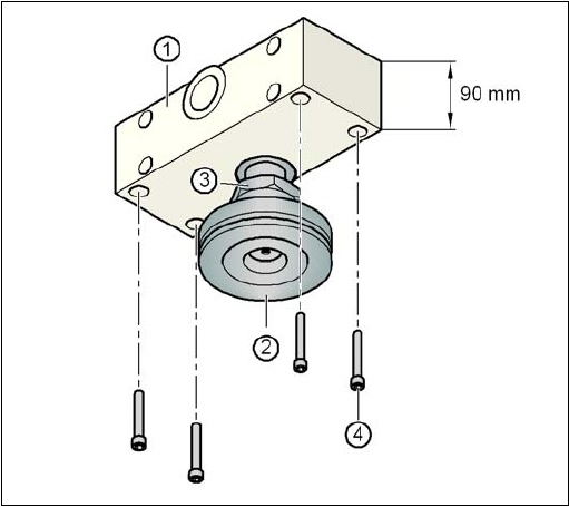
Make sure that the 90 mm side of the spacer is vertically aligned and the hole for the middle
machine foot indicates downwards.
4
4
4
4
4
4
4
4
4
4
4
4
Fig. 4.3 - 5 Aligning the spacer for a conveyor height of 900 mm
4
(1) Spacer height of 90 mm
(2) Middle machine foot
(3) Lock nut M24
(4) Hexagon socket head screw M12x80, 4x
Instruction manual SIPLACE X-Series S 4 Setting up and commissioning
From software version 713.0 Edition 11/2019 4.3 Setting up the placement machine
211
Screw the thread of the middle machine foot into the hole provided on the underside of the
spacer.
Align the two spacers on the machine underside as follows:
– The spacer opening on the pneumatic unit side points in the direction of board conveyor
travel (see item 4 in fig. 4.3 - 4
, page 209).
– The spacer opening on the power supply side points in the opposite direction to that of
conveyor travel (see item 3 in fig. 4.3 - 4
, page 209).
Fasten each of the two spacers with four hexagon socket-head screws M12x80 (see item 4
in fig. 4.3 - 5
). Use the screwdriver bit of size 10 mm.
Setting a board conveyor height of 930 and 950 mm 4
You also need the spacer for the board conveyor heights 930 mm and 950 mm.
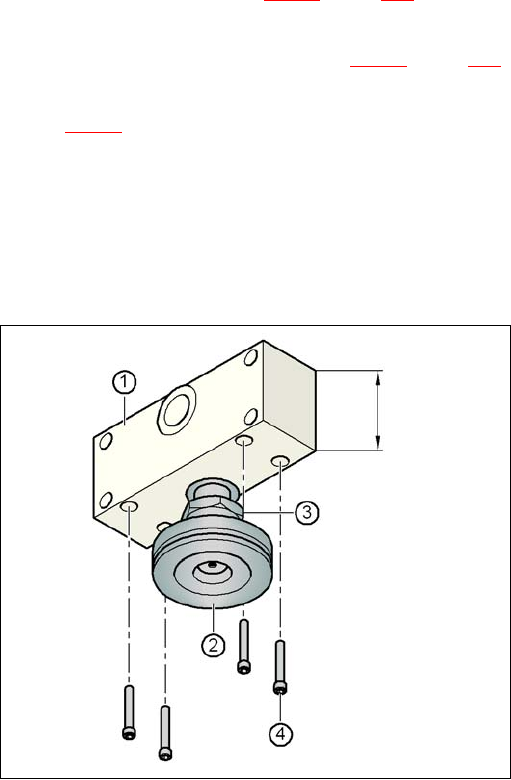
Make sure that the 122.5 mm side of the spacer is vertically aligned and the hole for the mid-
dle machine foot indicates downwards.
4
Fig. 4.3 - 6 Aligning the spacer for a conveyor heights of 930 and 950 mm
4
(1) Spacer height of 122.5 mm
(2) Machine foot
(3) Lock nut M24
(4) Hexagon socket head screw M12x80, 4x
122.5 mm
4 Setting up and commissioning Instruction manual SIPLACE X-Series S
4.3 Setting up the placement machine From software version 713.0 Edition 11/2019
212
Screw the thread of the middle machine foot into the hole provided on the underside of the
spacer.
Align both spacers as follows:
– The spacer opening on the pneumatic unit side points in the direction of board conveyor
travel (see item 4 in fig. 4.3 - 4
, page 209).
– The spacer opening on the power supply side points in the opposite direction to that of
conveyor travel (see item 3 in fig. 4.3 - 4
, page 209).
Fasten each of the two spacers with four hexagon socket-head screws M12x80 (see item 4
in fig. 4.3 - 6
). Use the screwdriver bit of size 10 mm.
4.3.6.2 Presetting the height of the outer machine feet
4
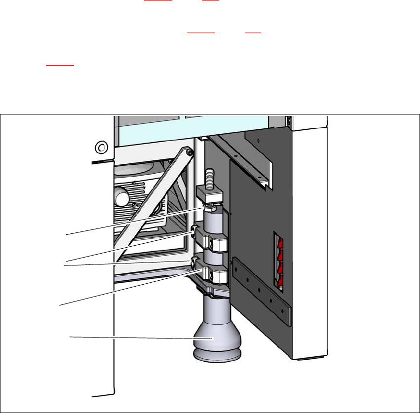
Fig. 4.3 - 7 Presetting the height of the outer machine feet
(1) Setting screw M24x2x120 for height adjustment
(2) Outer machine foot
(3) Clamping piece
(4) Hexagon socket-head screw M24x90
(4)
(2)
(1)
(3)