00198711-01_UM_X-Serie-S_EN.pdf - 第314页
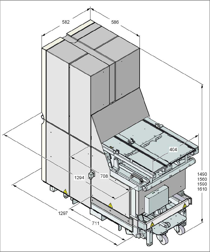
6 Station extensions Instruction manual SIPLACE X-Series S 6.4 Matrix tray changer From software versio n 713.0 Edition 11/2019 314 6.4.4.1 Dimensions 6 Fig. 6.4 - 1 Matrix tray changer , dimensions, all data in millimet…

Instruction manual SIPLACE X-Series S 6 Station extensions
From software version 713.0 Edition 11/2019 6.4 Matrix tray changer
313
6.4.3.2 Electrical ratings
6
6.4.3.3 Noise emissions
6
6.4.3.4 Permitted environmental factors
6
6.4.4 Installation notes for the MTC
In SIPLACE X2 S / X3 S / X4 S machines, an MTC can be docked onto location 2 in place of the
component trolley. To achieve this, the COT insert for the component trolley is replaced with the
docking unit for the MTC. If you want to use this MTC somewhere else, the free location can then
be configured again with a component trolley.
6
Supply voltage 3 x 200 V~ ± 5%; 50/60 Hz (Japan)
3 x 208 V~ ± 5%; 50/60 Hz (U.S.A.)
3 x 400 V~ ± 5%; 50/60 Hz (Europe)
Overall power 1.5 kW
Max. noise emissions 74 dB (A)
Room temperature Between 15°C and 35°C
Atmospheric humidity 30 to - 75 % (no higher than 45% on average to prevent
any possibility of condensation on the placement ma-
chine.)
PLEASE NOTE
Configuration options for MTC
– The MTC can not be configured with a CPP head.
– The MTC can only be configured at location 2 in SIPLACE X2 S / X3 S / X4 S ma-
chines.
– SIPLACE X2 S / X3 S / X4 S machines must have a service flap installed. See “Po-
sition of protective switches on the placement machine” on page 81.
– The MTC can be configured with the Twin Head and the stationary cameras of type
33, 25 or the 3D coplanarity sensor.
– Only 12 nozzle magazines can be used for configurations with an MTC.
6 Station extensions Instruction manual SIPLACE X-Series S
6.4 Matrix tray changer From software version 713.0 Edition 11/2019
314
6.4.4.1 Dimensions
6
Fig. 6.4 - 1 Matrix tray changer, dimensions, all data in millimeters
Instruction manual SIPLACE X-Series S 6 Station extensions
From software version 713.0 Edition 11/2019 6.4 Matrix tray changer
315
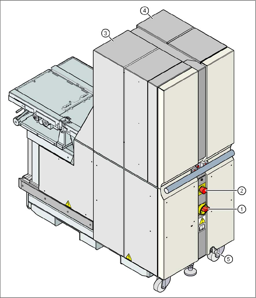
6.4.4.2 Controls
6
Fig. 6.4 - 2 Matrix tray changer, back view
(1) Main switch
(2) EMERGENCY STOP button
(3) Tower 1 for accommodating max. 30 waffle pack tray carriers (up to 60 JEDEC trays)
(4) Tower 2 for accommodating max. 40 waffle pack tray carriers (up to 40 JEDEC trays)
(5) Attachment point for crank used to adjust the matrix tray changer height