00198711-01_UM_X-Serie-S_EN.pdf - 第204页
4 Setting up and commissioning Instruct ion manual SIPLACE X-Series S 4.3 Setting up the placement machine From software version 713.0 Edition 11/2019 204 4 4 4 4 WARNING Risk of damage due to excessive fork spacing! Inc…
Instruction manual SIPLACE X-Series S 4 Setting up and commissioning
From software version 713.0 Edition 11/2019 4.3 Setting up the placement machine
203
4.3.2 Lifting and transporting the placement machine with the fork lift truck
4
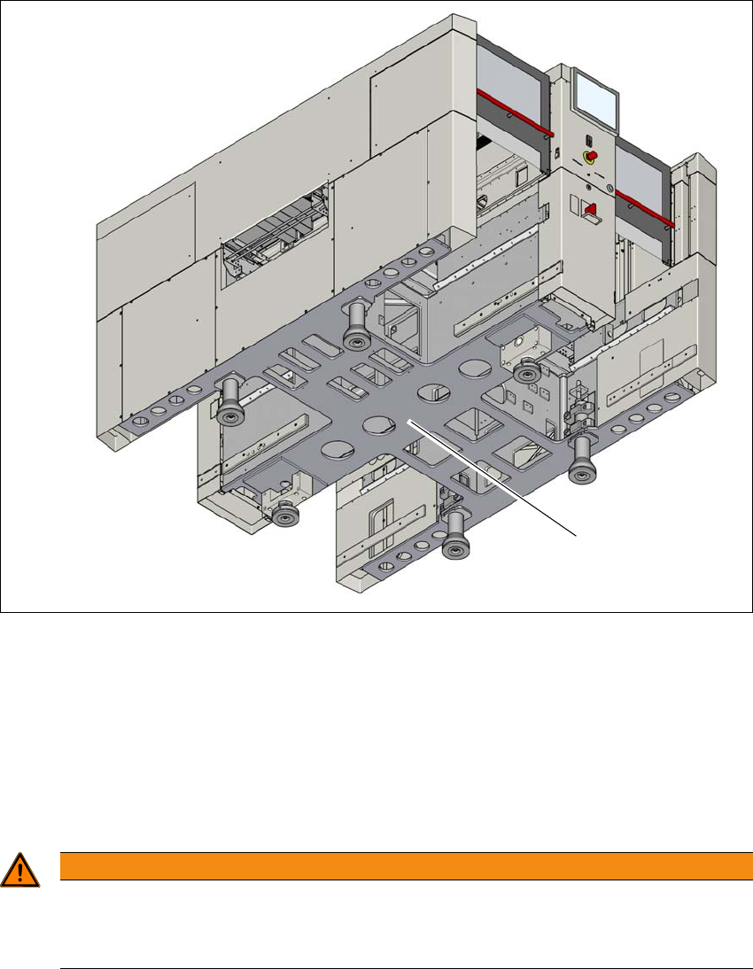
Fig. 4.3 - 1 Contact surfaces - forks parallel to the direction of PCB transport (example of SIPLACE X2 S / X3 S / X4
S shown)
(1) Contact surface for fork lift truck forks
Position the fork-lift truck at right angles to the PCB conveyor and open the forks until the con-
tact surfaces of the placement machine lie evenly on the forks.
Please note the following warnings before you raise the placement machine in order to avoid
irreversible damage to the placement machine:
4
WARNING
Aligning the forks
– The forks must be aligned parallel to the PCB conveyor.
– The forks must be aligned parallel to the placement machine.
(1)
4 Setting up and commissioning Instruction manual SIPLACE X-Series S
4.3 Setting up the placement machine From software version 713.0 Edition 11/2019
204
4
4
4
4
WARNING
Risk of damage due to excessive fork spacing!
Increased fork spacing, which means that the placement machine is raised at points out-
side its contact surface, can lead to deformation of the placement machine frame and
cause damage to cables and lines.
The forks may only be opened to a degree which ensures that they are still within
the contact area of the machine underside (see fig. 4.1 - 3
, page 189).
WARNING
Risk of damage due to one-sided loading!
One-sided loading of the machine feet e.g. from tilting the placement machine, can lead
to deformation of the machine feet fixtures.
Make sure that the forks are evenly loaded when you lift the placement machine.
Use a firm support layer between the forks and the placement machine.
Enlist the help of a second person to watch while you lift the placement machine and
make sure that the placement machine does not tip over to one side.
WARNING
Risk of damage!
The thread for the machine feet in the placement machine frame could be damaged by
it being dragged along the floor or from impact.
When you are transporting the machine, make sure that all the feet are clear of the
floor.
WARNING
Risk of damaging the exhaust air duct for the vacuum pump!
Vacuum pumps can be fitted in placement area 1. The exhaust air duct is fitted under the
machine base. This exhaust air duct could be damaged during transportation with the
fork-lift.
Dismantle the exhaust air duct before you transport the placement machine with the
fork-lift.

Instruction manual SIPLACE X-Series S 4 Setting up and commissioning
From software version 713.0 Edition 11/2019 4.3 Setting up the placement machine
205
4.3.3 Fitting attached parts
The placement machine is delivered with the monitor and indicator lamp dismantled. To fit these
components, proceed as follows:
– To fit the indicator lamps see section 4.3.3.2
, page 205
– To fit the monitor see section 4.3.3.3, page 205
– Hook up the keyboard fixture and connect the keyboard (optional)
4.3.3.1 Checking and setting the protective cover switch
Check the function of the protective cover switch (see 2.5.1 on page 67).
Adjust the protective cover switch if necessary (see service manual).
4.3.3.2 Fitting the indicator lamp
Insert the indicator lamp into the hole until the lamp tube projects sufficiently into the terminal
beneath.
Connect the cable for the indicator lamps to the plug. The cable with plug is located in the
tube.
Tighten the two screws on the terminal so that the indicator lamp is clamped into place.
4.3.3.3 Fit the monitors
Use the 4 fastening screws to fix the monitor to the monitor mount and then connect the cable.
Check the cable connections.