00198711-01_UM_X-Serie-S_EN.pdf - 第19页
Instruction manual SIPLACE X-Series S 1 Introduction From software version 713.0 Edition 11/201 9 1.2 Placement machine description 19 1.2 Placement machine description 1.2.1 SIPLACE X4i S 1 Fig. 1.2 - 1 SIPLACE X4i S pl…
1 Introduction Instruction manual SIPLACE X-Series S
1.1 Important notes on the instruction manual From software version 713.0 Edition 11/2019
18
C&P20 P2 Collect&Place head with 20 segments, SIPLACE SpeedStar for top placement
performance
CPP Collect&Pick&Place head, SIPLACE MultiStar CPP
DCA Direct chip attach
DC Dual conveyor
EDIF Energy and data interface
ESD Electrostatically-sensitive group of components
EMC Electromagnetic compatibility
ESD Electrostatic sensitive device
SC Single conveyor
FC Flip chip
WT Waffle pack tray
WTC Waffle pack tray carrier
GCU Gantry control unit
GND Ground
I-Placement Independent placement
JTF JEDEC Tray Feeder
LBO Long Board Option
PCB Printed circuit board
MCS Machine capability study
MHCU Head control unit
MTC Matrix tray changer
P&P Pick&Place
P&P1 Pick&Place module 1
P&P2 Pick&Place module 2
NC Nozzle changer
SMD Surface mounted device
SC Station computer
TH Twin Pick&Place head, SIPLACE TwinStar
VS Vision system
WPC Waffle pack changer
Instruction manual SIPLACE X-Series S 1 Introduction
From software version 713.0 Edition 11/2019 1.2 Placement machine description
19
1.2 Placement machine description
1.2.1 SIPLACE X4i S
1
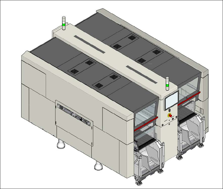
Fig. 1.2 - 1 SIPLACE X4i S placement machine
The SIPLACE X4i S placement machine is distinguished by
– High precision,
– Intelligent placement optimization,
– Intelligent configuration strategies,
– Placement performance up to the high end process range

1 Introduction Instruction manual SIPLACE X-Series S
1.2 Placement machine description From software version 713.0 Edition 11/2019
20
Three placement methods are possible for processing the components:
– Collect&Place,
– Pick&Place and
– A combination of Collect&Place and Pick&Place (mixed mode).
The SIPLACE X4i S placement machine has four gantries. The two gantries in placement area 1
and the two gantries in placement area 2 point inwards.
These can be quickly and accurately positioned by linear motors, moving independently of one
another in the X and Y directions.
The SIPLACE X4i S placement machine has two placement areas, one single conveyor or one
dual conveyor. Two boards can be placed at the same time on dual conveyors.
There are four locations available for supplying components. These can be fitted with component
trolleys and configured with up to 40 tracks. At locations 2/3 or 1/4, the table positions for the rel-
evant placement area can be configured on the innermost or outermost position.
1.2.1.1 Overview of placement head configuration
1
CPP_H = SIPLACE Multistar CPP in high assembly position
CPP_L = SIPLACE Multistar CPP in low assembly position
Placement area 1 Placement area 2
C&P20 P / C&P20 P C&P20 P / C&P20 P
C&P20 P / C&P20 P CPP_L/CPP_L
C&P20 P / C&P20 P TH / TH
C&P20 P / C&P20 P CPP_H/TH
C&P20 P2 / C&P20 P2 C&P20 P2/C&P20 P2
C&P20 P2 / C&P20 P2 CPP_L/CPP_L
C&P20 P2 / C&P20 P2 TH / TH
C&P20 P2 / C&P20 P2 CPP_H/TH
CPP_L/CPP_L CPP_L/CPP_L
CPP_L/CPP_L CPP_H/TH
CPP_L/CPP_L TH / TH