00198711-01_UM_X-Serie-S_EN.pdf - 第148页
3 Technical data and assemblies Instruction manual SIPLACE X-Series 3.7 PCB conveyor system From software version 713.0 Edition 11/2019 148 3.7.5 Definition of PCB warp age 3.7.5.1 PCB warp age on the conveyor PCB warpag…
Instruction manual SIPLACE X-Series 3 Technical data and assemblies
From software version 713.0 Edition 11/2019 3.7 PCB conveyor system
147
3.7.3.4 Synchronous transport mode
In synchronous mode, two PCBs of the same size are transported into the placement position at
the same time. They are processed as a common panel. When using products with greatly differ-
ing placement content, common optimization increases the performance of the whole content on
both boards.
The time needed to transport the board is reduced as two boards are always transported at the
same time. It also ensures better utilization of the nozzle configuration.
PCBs on conveyor tracks 1 and 2 are moved synchronously onto the conveyor sections (i.e. the
conveyors are controlled synchronously, but independently of one another). The components to
be placed on conveyor tracks 1 and 2 must be organized into a panel via two subpanels.
If only one conveyor lane is occupied at the beginning of placement, this single use of the con-
veyor lane will be identified as "not to be placed".
If the dual conveyor is operated in synchronous mode, the ‘PCB whispering down the line’ option
is deactivated. The "Global bad fiducial" option cannot be used.
3.7.3.5 I-Placement
In addition to synchronous and asynchronous conveyor modes, I-Placement is also available. In
this mode, the two heads work simultaneously and populate a PCB totally independently of one
another. This further increases the output.
3.7.4 Controlling and width adjustment
3.7.4.1 Controlling using the Single Functions menu
The online help contains information on controlling the PCB conveyor system and on the Single
Functions menu.
3.7.4.2 Automatic width adjustment
When the command is received, the conveyor belts are set to the desired width. Different widths
are possible for a dual conveyor.
See the Online Help for detailed information about changing the conveyor track width.
3 Technical data and assemblies Instruction manual SIPLACE X-Series
3.7 PCB conveyor system From software version 713.0 Edition 11/2019
148
3.7.5 Definition of PCB warpage
3.7.5.1 PCB warpage on the conveyor
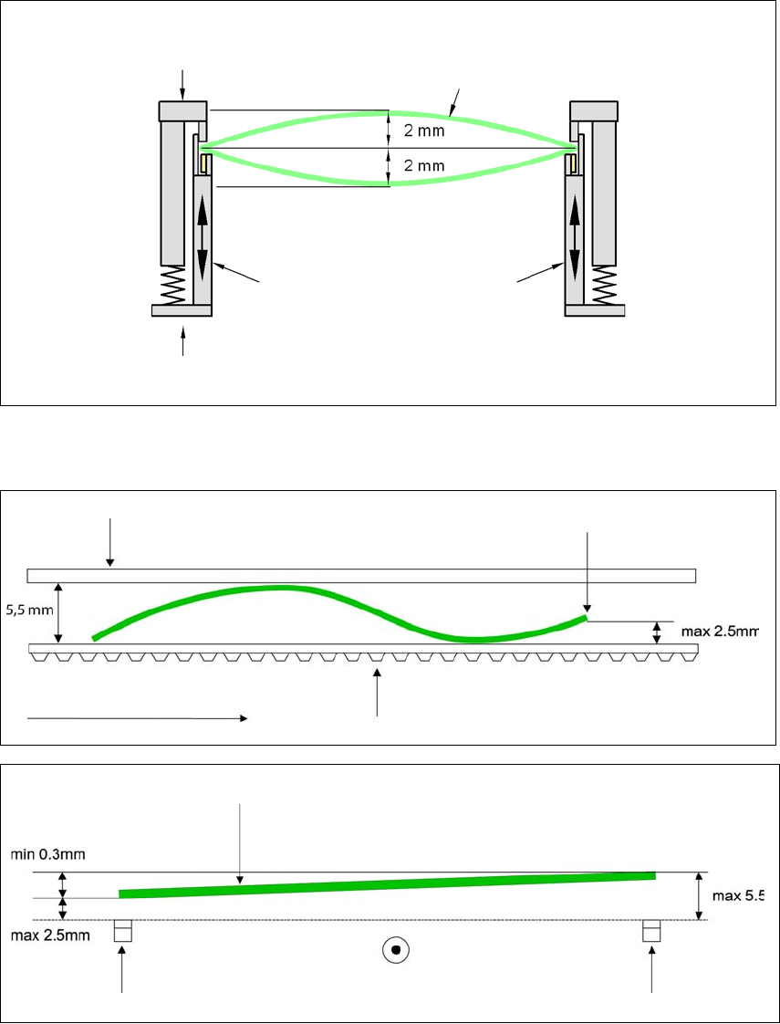
PCB warpage across the direction of travel max. 1 % of the PCB diagonal, but not exceeding 2 mm
3
PCB warpage in the direction of transport + PCB thickness < 5.5 mm. Bending up of board edge
max. 2.5 mm.
3
3
Fixed clamped edge
Movable clamping device
Printed circuit board
Conveyor side wall
Fixed clamped edge
Conveyor belt
PCB transport direction
Front board edge
Front board edge
Right conveyor belt
Left conveyor belt
PCB transport direction
Instruction manual SIPLACE X-Series 3 Technical data and assemblies
From software version 713.0 Edition 11/2019 3.7 PCB conveyor system
149
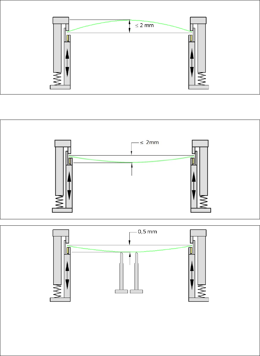
3.7.5.2 PCB warpage during placement
3
3
Changes in the surface position are automatically applied by the functions for learning the height.
3
3
PCB warpage up, max. 2.5 mm
PCB warpage down, max. 2.5 mm
PCB support
To avoid impairing the placement quality and speed, we recommend using a PCB support e.g.
Smart Pin Support so that the PCB warpage downwards does not exceed 0.5 mm.