00198711-01_UM_X-Serie-S_EN.pdf - 第140页
3 Technical data and assemblies Instruction manual SIPLACE X-Series 3.6 Gantry system From software version 713.0 Edition 11/2019 140 3.6.5 X axis structure 3 Fig. 3.6 - 5 Design of X axis - view of head mount (1) Head m…
Instruction manual SIPLACE X-Series 3 Technical data and assemblies
From software version 713.0 Edition 11/2019 3.6 Gantry system
139
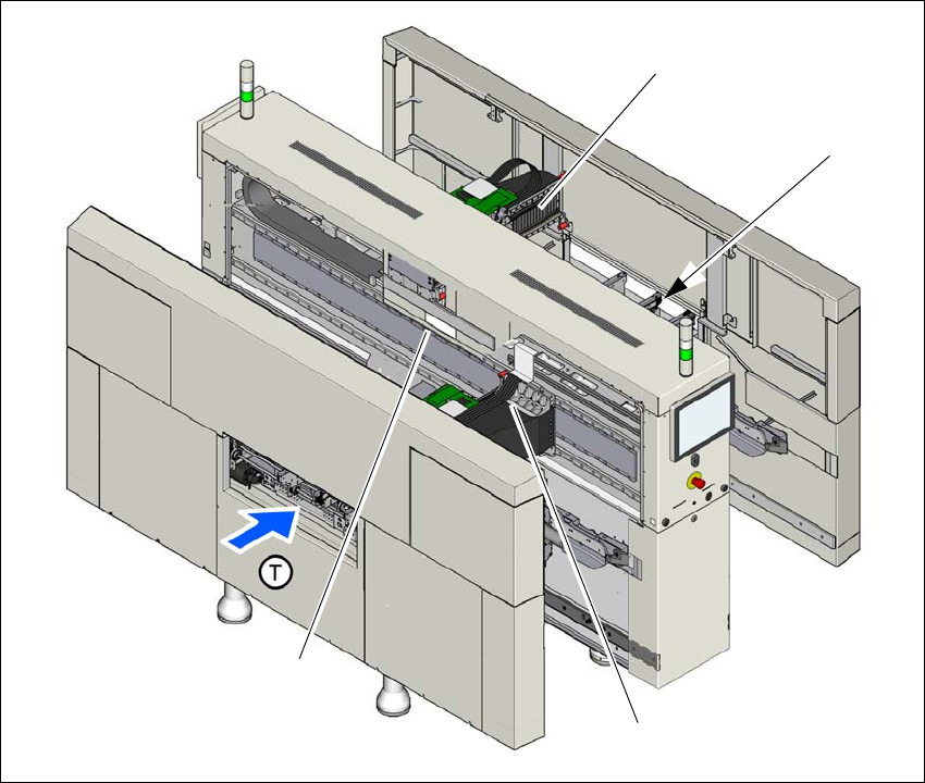
3.6.4 Position of gantries in SIPLACE X2 S
3
Fig. 3.6 - 4 Position of gantries - SIPLACE X2 S
(1) Y axis, gantry 1
(2) X axis, gantry 1
(3) X axis, gantry 2 (covered)
(4) X axis, gantry 2
(T) Direction of PCB transport
(1)
(3)
(2)
(4)
3 Technical data and assemblies Instruction manual SIPLACE X-Series
3.6 Gantry system From software version 713.0 Edition 11/2019
140
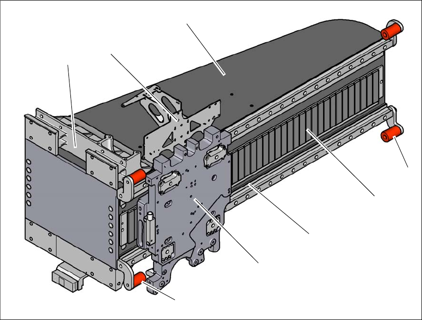
3.6.5 X axis structure
3
Fig. 3.6 - 5 Design of X axis - view of head mount
(1) Head mount with X axis linear motor (primary part)
(2) Y linear motor with fixed bearing (primary part)
(3) Guidance system with permanent magnet (secondary part of the X linear motor)
(4) End position bumper (4x)
(5) Gantry arm
(6) Head board mount
(7) Length measurement system
(4)
(3)
(1)
(5)
(2)
(6)
(4)
(7)
Instruction manual SIPLACE X-Series 3 Technical data and assemblies
From software version 713.0 Edition 11/2019 3.6 Gantry system
141
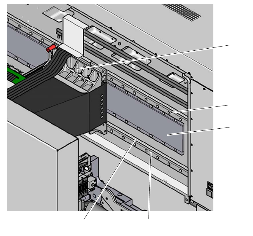
3.6.6 Y axis structure
3
Fig. 3.6 - 6 Y-axis structure (example of SIPLACE X2 S / X3 S / X4 S shown)
The Y axis essentially consists of the following main modules:
(1) Y linear motors (primary part) on the X axis with fixed and loose bearing mounted
(2) Permanent magnet (secondary part of the X-axis linear motor)
(3) Linear distance measuring system
(4) Guidance system
(1)
(4)
(2)
(3)
(4)