00198711-01_UM_X-Serie-S_EN.pdf - 第178页
3 Technical data and assemblies Instruction manual SIPLACE X-Series 3.9 Component trolley From softwa re version 713.0 Edition 11/2019 178 3 Fig. 3.9 - 7 SIPLACE X-Series S changeover table, front view (1) Locking latc h…
Instruction manual SIPLACE X-Series 3 Technical data and assemblies
From software version 713.0 Edition 11/2019 3.9 Component trolley
177
3.9.6 SIPLACE X-Series S changeover table
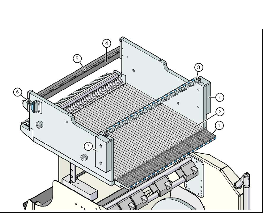
The front slider guides of the feeder modules are placed on the insertion aid. As it is pushed in,
the guides of the feeder module slide on the guide profile as far as the stop bar. A centering hole
on the stop bar holds the "front" centering pin of the X feeder module. At the same time, the
changeover table locking latch (item 1 in fig. 3.9 - 7
, page 178) engages onto the locking roller of
the feeder module. The "back" centering pin on the top of the feeder module is held by the recess
in the centering bar.
3
Fig. 3.9 - 6 Changeover table, SIPLACE X-Series S, rear view
(1) Insertion aid
(2) Guide profile (Ω profile)
(3) Centering bar for holding the "back" centering pin for X feeder modules
(4) Stop bar
(5) Centering holes
(6) Contact for switching the safety switch of the EMERGENCY STOP circuit
(7) Hand guard
3 Technical data and assemblies Instruction manual SIPLACE X-Series
3.9 Component trolley From software version 713.0 Edition 11/2019
178
3
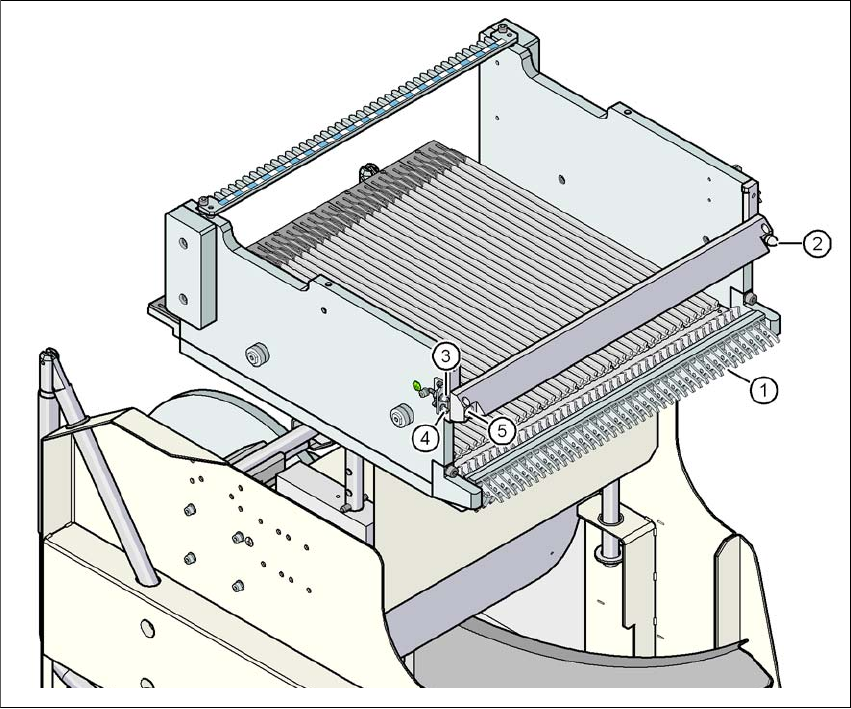
Fig. 3.9 - 7 SIPLACE X-Series S changeover table, front view
(1) Locking latches
(2) Centering pin on the changeover table
(3) Compressed air coupling
(4) Earthing (ground) pin
(5) Centering hole on the changeover table
Instruction manual SIPLACE X-Series 3 Technical data and assemblies
From software version 713.0 Edition 11/2019 3.9 Component trolley
179
3.9.7 Mount of additional tape reel
3
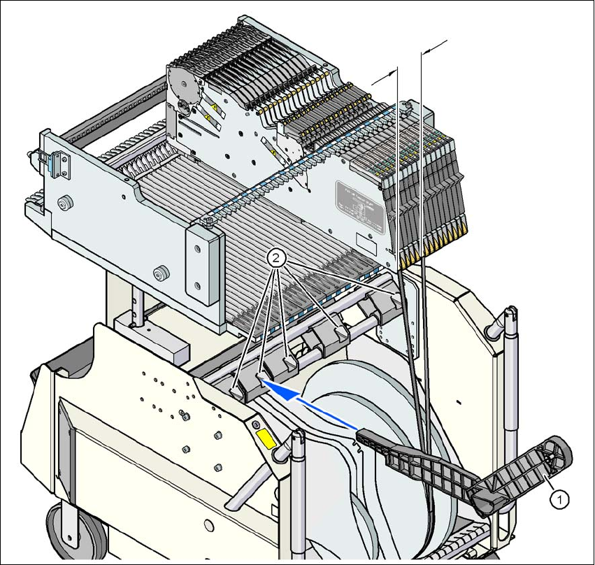
Fig. 3.9 - 8 Mount for additional tape reel (X-Series S)
(1) Mount of additional tape reel, item no. 00141217-xx
(2) Mounting device for the support
X-Series S feeder modules can process component tapes without problems if the lateral offset be-
tween the feeder module and the tape reel does not exceed 60 mm. If a predefined setup means
that the maximum permitted offset cannot be maintained, we recommend that you use the mount
for an additional tape reel (item 1). Simply insert the mount into the holder (item 2) and push it until
the offset is less than the maximum permitted value of 60 mm. The component trolley has 5 hold-
ers in total. Each tape reel mount can hold 2 tape reels, which means that up to ten 15" (381 mm)
reels can be positioned above the tape container.
Max. 60 mm