00191369-01.pdf - 第105页
User’s Manual SIPLACE HS-50 3 Introduction and Basic Concepts Software Version SR.501.xx Edition 01/99 3.2 Principles of the Graphic User Interface 103 $ ERUWSURFHVV LQJ Å Click t he corr espon ding PCB icon . If th…
3 Introduction and Basic Concepts User’s Manual SIPLACE HS-50
3.2 Principles of the Graphic User Interface Software Version SR.501.xx Edition 01/99
102
&RQWLQXHSURFHVVLQJ
This icon is displayed after "Stop processing PCB" or after a machine stop.
(The triangles in the icon move continuously from left to right.)
Click this icon to continue the interrupted operation once the error has been successfully elimi-
nated.
Å Click the icon .
Processing is now continued.
3URFHVVLQJ3&%
The PCB has been taken up be the system and is being processed. The PCB icon is displayed
in blue-green.
3URFHVVLQJRI3&%VWRSSHG
If processing of the PCB has been interrupted using "Stop processing PCB"" or has
been interrupted after a fatal error or because the Stop button has been pressed, the PCB icon
is again displayed in blue-green but now has contoured edges.
You can continue processing by clicking
or abort it by clicking the PCB icon.
NOTE
The procedure used to abort processing is described below.
User’s Manual SIPLACE HS-50 3 Introduction and Basic Concepts
Software Version SR.501.xx Edition 01/99 3.2 Principles of the Graphic User Interface
103
$ ERUWSURFHVVLQJ
Å Click the corresponding PCB icon .
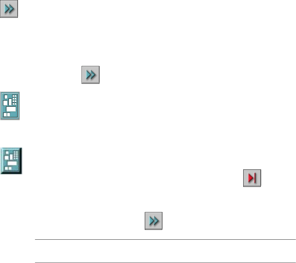
If the PCB is located on processing conveyor 2, the following dialog box is opened.
Å Click the checkbox "Abort processing PCB".
Å Click the $FFHSW button.
Processing of the PCB is aborted.
The incompletely assembled PCB is transported to the output conveyor and the operator
is requested to remove it by hand.
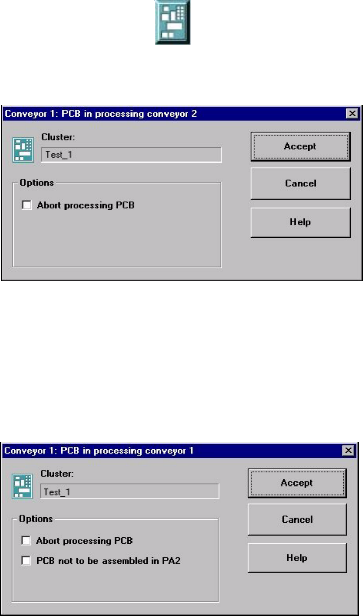
If the PCB is located on processing conveyor 1, the following dialog box is opened.
3 Introduction and Basic Concepts User’s Manual SIPLACE HS-50
3.2 Principles of the Graphic User Interface Software Version SR.501.xx Edition 01/99
104
Å Check the box "Abort processing PCB" if the PCB is to be transported to the output
conveyor without further processing.
Å Check the box "PCB not to be assembled in PA2" if the PCB is to be processed on
processing conveyor 1 and is then to be transported to the output conveyor without being
processed on processing conveyor 2.
Å Click the $FFHSW button.
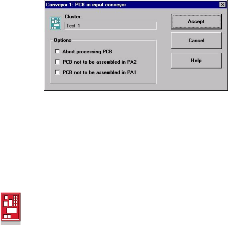
If the PCB is located on the input conveyor, the following dialog box is opened.
Å Check the box "Abort processing PCB" if the PCB is to be transported to the output
conveyor without further processing.
Å Check the box "PCB not to be assembled in PA2" if the PCB is to be processed on
processing conveyor 1 only and is then to be transported to the output conveyor without
being processed on processing conveyor 2.
Å Check the box "PCB not to be assembled in PA1" if the PCB is to be transported through
processing conveyor 1 without being processed and is then to be processed on processing
conveyor 2.
Å Click the $FFHSW button.
3URFHVVLQJRI3&%DERUWHG
If processing of the PCB has been aborted by a click on the PCB icon (see example above),
the color of the PCB icon changes to red.
The icon is also displayed in red if a PCB is manually placed on processing conveyor 1 or 2.
The PCB is not recognized by the system and is transported to the output conveyor.