00191369-01.pdf - 第281页
User Manual HS-50 6 Vision functions Software-Version 5.01Edition 01/99 6.6 Test Component 279 0HDVXUH0RGH2SWL RQ NOTE This opti on can onl y be a ctivated whe n a GF n umber ha s been loaded . The senso r…
6 Vision functions User Manual HS-50
6.6 Test Component Software-Version 5.01 Edition 01/99
278
*UDSKLFSUHVHQWDWLRQ RIWKHWDE OH
In the diagram
– the abscissae (x axis) represent the input values range, subdivided into sections.
– the ordinates (y axis) represent the output values with their color allocation.
%XWWRQV
Å $FFHSW
Click on the $FFHSW button to save the settings. The option box will then close.
Å &DQFH O
With &DQFHO you can discard the settings. The option box will then close.
Å +HOS
With the +HOS button you can access explanatory material regarding the on-screen presenta-
tion.
Å 1XPEHUinput field
You can choose the number of sections
Å by entering the numerical value directly into the display field, or
Å by moving the scroll field in the scroll bar to the right or left using the mouse. In this way you
can run back and forth through the values range (1 - 5), or
Å by clicking on the lefthand or right-hand arrow on the scroll bar. In this way you can increase
or decrease the number of selections.
3URJUDPPLQJWKHWUDQVIRUPDWLRQWDEOH
Å Specifying the output values
Position the mouse pointer over the ends of the transformation lines of each section. The ends
are marked with small horizontal lines. A vertical double arrow will then appear on the screen.
Click on the lefthand mouse key and move the arrow upwards or downwards. This will move
the selected end of the transformation line and the numerical value will be displayed at 287
%HJLQor 287(QG.
Å Selecting the section limits
The graphical representation in Fig. 6.6 - 30 on page 6 - 277 shows equidistant section limits
with the ranges 0 - 50, 51 - 100 and so on. You can change these section limits if you wish.
However limits 0 and 255 are permanently allocated and cannot therefore be moved.
Position the mouse pointer on a section limit (but not 0 and 255). A horizontal double arrow will
appear on the screen. Hold down the lefthand mouse pointer and use it to drag the section limit
in the direction you want. The corresponding numerical value will be displayed at ,1.
Å Once you have programmed your transformation table you can quit the option box by clicking
on $FFHSW or &DQFHO.

User Manual HS-50 6 Vision functions
Software-Version 5.01Edition 01/99 6.6 Test Component
279
0HDVXUH0RGH2SWLRQ
NOTE
This option can only be activated when a GF number has been loaded.
The sensor-specific part of the package form includes a data structure with measurement condi-
tions for the components. In this menu you can manipulate these measurement conditions. The
menu options are primarily intended for the creation of your own user-specified GF file.
This option allows you to
Å select and activate a particular measurement method or combination of several measurement
methods
Å deactivate individual measurement methods, and
Å change the hex parameters belonging to each measurement method.
The hex parameters for the individual measuring methods can be modified in two ways:
Å either indirectly, i.e. menu-driven
You will be guided by the package form manipulator by means of setting menus and explana-
tory text in order to obtain the desired measuring results quickly and accurately.
Å or directly, i.e. you enter the necessary hex parameters directly into the ’Measuring mode 2’
input box.
NOTE
Please note that entering the hex values directly requires considerable knowledge of the
measuring method sequence.
If you intend to enter or modify hex values directly, please contact Siemens Service first and
do not enter the bit-coded hex values until you have spoken to the Service Department.
We recommend that you generally use the menu-driven package form manipulator.
6 Vision functions User Manual HS-50
6.6 Test Component Software-Version 5.01 Edition 01/99
280
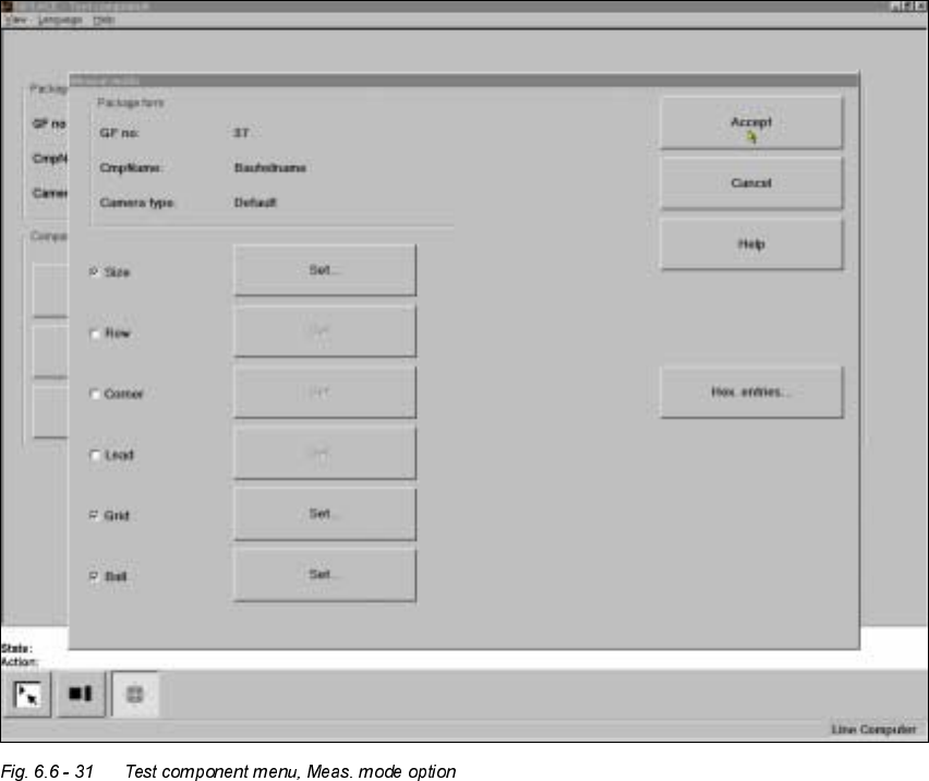
0HDVXULQJPRGHPHQX
Click on the ’Measuringmode’ field to call up the 0HDVXULQJPRGH menu.
– In the left column of the box, the desired measuring method can be activated or deactivated
by clicking with the mouse. A cross indicates that you have activated the measuring method.
The ‘Setting' field for calling up the sub-menu changes from grey to black.
Use the ‘Hex input’ field to call up the ‘Measuring mode 2’ input menu for directly entering hex
values. Please follow the instructions on page 6 - 279.
Å Select ‘Accept’ to close the ‘Measuring mode’ menu. The modified measuring conditions will
be entered into the package form file on the station computer.
Å Select ‘Abort’ to interrupt the operation without transferring the data and to return to the ‘Test
component’ menu.