00191369-01.pdf - 第331页
User’s Manual SIPLACE HS-50 7 What schould you do ... Software Version S R.501.xx Edition 01/99 7.7 Changing the set-up 329 :KDW\RX VKRXOGQRWHZ KH QFKDQJLQJWKHFRPSRQHQWWDEOH Å Set up the feeder modules in t…

7 What schould you do ... User’s Manual SIPLACE HS-50
7.7 Changing the set-up Software Version SR.501.xx Edition 01/99
328
&KDQJLQJWKHVHWXS
Before changing the set-up, print out the instructions regarding changing the set-up on the printer
of the line computer as described in chapter 14 of the ’UNIX line computer’ User’s Manual.
:KDW\RXVKRXOGQRWHZKHQFKDQJLQJWKHIHH GHUPRGXOHV
Å Handle the feeder modules carefully when you insert them into or remove them from the com-
ponent table. Do not allow the supporting surfaces of the feeder modules to bang against the
edges of the component table.
Å Vacuum the supporting surfaces of the feeder modules and clean the surface of the component
table when necessary according to the instructions in the maintenance manual.
RISK OF INJURY
Avoid removing components from the magnetic rail of the component table with your fingers
because you may hurt yourself with tiny splinters of metal.
Å Remove loose components with a short-bristled brush.
User’s Manual SIPLACE HS-50 7 What schould you do ...
Software Version SR.501.xx Edition 01/99 7.7 Changing the set-up
329
:KDW\RXVKRXOGQRWHZKHQFKDQJLQJWKHFRPSRQHQWWDEOH
Å Set up the feeder modules in the external set-up area according to the changeover instruc-
tions. Follow the preliminary set-up instructions in section 7.6
.
WARNING
NEVER place your hand in one of the gaps between the component change table and the ma-
chine stand while the machine is running (see Fig. 7.7 - 1, No. 8).
WARNING
The power supply cable for the component table may only be plugged into or unplugged from the
socket on the placement station if the component table is correctly inserted in the set-up area of
the station.
WARNING
It is prohibited to plug the power supply cable for the component table in the socket on the place-
ment station to operate the component table when away from the station via the compressed air
controller.
7 What schould you do ... User’s Manual SIPLACE HS-50
7.7 Changing the set-up Software Version SR.501.xx Edition 01/99
330
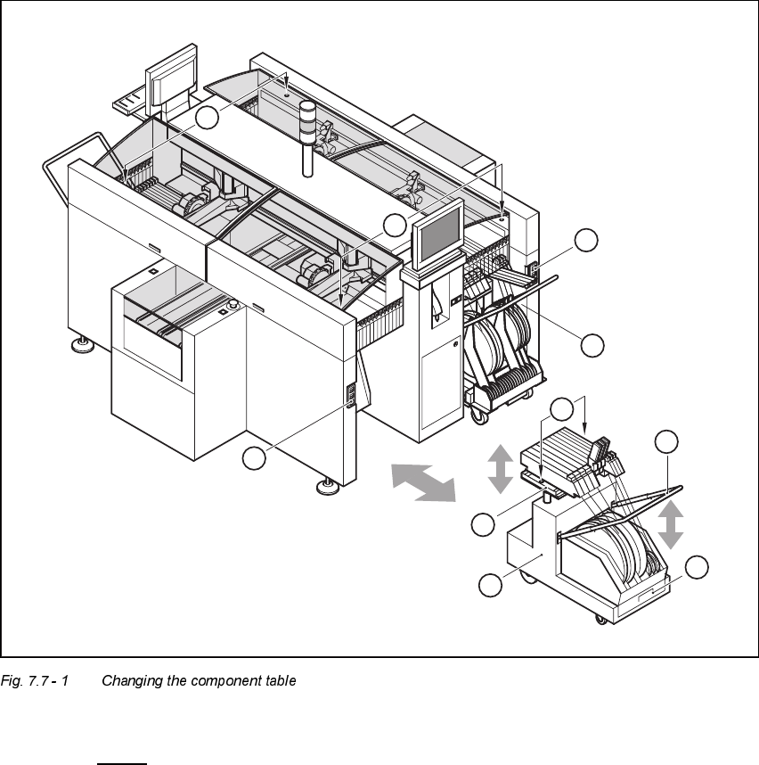
.H\WR)LJ
7.7 - 1
(1) Button for raising and lowering the component tabletop
(2) Socket for connecting the power supply cable
(3) Component tabletop (can be raised and lowered)
(4) Component table
(5) Bracket
(6) Tape waste container
(7) Centered bore hole for the centering pin
(8) Gap between the component table and machine stand
6
5
4
3
2
1
7
2
1
8