00191369-01.pdf - 第381页
User Manual HS-50 11 Station extensions / options Software Vers ion 5.0101/99 Issue 11.1 HS-50 nozzle c hanger 379 6W DWLRQH[WHQVLRQVRSWLRQV +6QR]]OH FKDQJHU 2YHUY LHZ The placem ent syste m i…
10 Component handling User Manual HS-50
10.6 Component changeover tables Software-Version 5.01 01/99 Issue
378
User Manual HS-50 11 Station extensions / options
Software Version 5.0101/99 Issue 11.1 HS-50 nozzle changer
379
6WDWLRQH[WHQVLRQVRSWLRQV
+6QR]]OH FKDQJHU
2YHUYLHZ
The placement system is supplied as standard with four revolver heads and four nozzle changers.
As an option, a second nozzle changer can be installed for each revolver head.
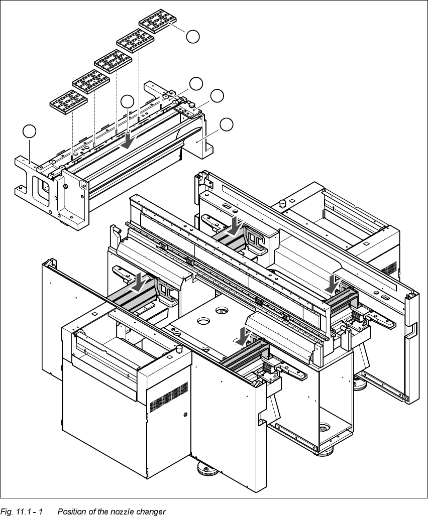
The nozzle changer consists of at least one, and up to five magazines, each with 12 nozzle gara-
ges (see Fig. 11.1 - 1). The magazines are seated on a common support and each magazine is
centered using two parallel pins and fixed in place with clips.
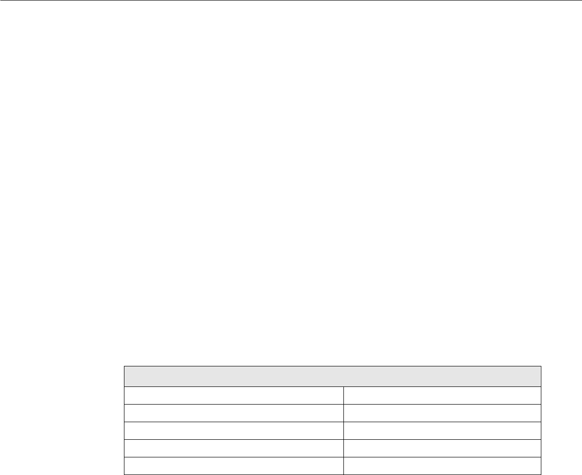
7HFKQLFDOGDWD
1R]]OHFKDQJHUIRUWKHUHYROYHUKHDG
Dimensions (length x width x height) 472.5 mm x 64 mm x 90 mm
Number of nozzle garages Min. 12 / max. 60
Nozzle types 7xx
Time required to open and close the locking plate < 200 ms
Pneumatic circuit Air line 5.3 bar
11 Station extensions / options User Manual HS-50
11.1 HS-50 nozzle changer Software Version 5.01 01/99 Issue
380
.H\WR)LJ
(1) Used tape guide channel (2) Nozzle discarding device
(3) Nozzle changer (4) Nozzle magazines
(5) Location for optional 2nd nozzle changer
(6) Container for discarded nozzles
1
2
3
4
5
6