00191369-01.pdf - 第109页
User’s Manual SIPLACE HS-50 3 Introduction and Basic Concepts Software Version S R.501.xx Edition 01/99 3.3 User Interface - Views and M enus 107 8VHU,QWHUIDFH9 LHZVDQG0HQXV 9L HZ V T o perfo rm a particu…
3 Introduction and Basic Concepts User’s Manual SIPLACE HS-50
3.2 Principles of the Graphic User Interface Software Version SR.501.xx Edition 01/99
106
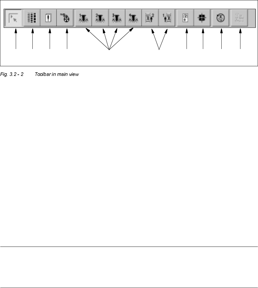
7RROEDULQ0DLQ9LHZ
.H\WR)LJXUH
(1) Main view
(2) Set-up, placement functions (for a description see Chapter 4)
(3) Error, placement functions (for a description see Chapter 4)
(4) Component feeder, placement functions(for a description see Chapter 4)
(5) Gantry 1 to 4, single functions (for a description see Chapter 5)
(6) Conveyor 1 and 2, single functions (for a description see Chapter 5)
(7) Teach fiducials, vision functions (for a description see Chapter 6)
(8) Test component, vision functions (for a description see Chapter 6)
(9) Start SITEST test program (for a description see User’s Manual
"Test Program SITEST")
(10) GEM interface (for a description see Chapter 13)
NOTES to points 6 and 10
The single functions for Conveyor 2 can only be called if a twin conveyor has been configured.
The GEM interface functions cannot be called unless this has been configured.
The "GEM Interface" option cannot be configured in the current software version.
Å Click the required button in the toolbar.
The user interface is switched to the corresponding view.
The button corresponding to the view which is currently active itself becomes inactive.
1 8 9 10765432

User’s Manual SIPLACE HS-50 3 Introduction and Basic Concepts
Software Version SR.501.xx Edition 01/99 3.3 User Interface - Views and Menus
107
8VHU,QWHUIDFH9LHZVDQG0HQXV
9L HZV
To perform a particular operation at a particular moment via the user interface, you may need
to switch this to a different view. You can do this by clicking the appropriate toolbar button (see
section 3.2.2.2) or by selecting the corresponding menu item in the "View" menu (see section
3.3.2.2).
NOTE
For a description of the functions available in the various views, refer to the chapters which
explain the procedures applicable to the operations to be performed (e.g. "Refilling Empty
Tracks", Chapter 4).

3 Introduction and Basic Concepts User’s Manual SIPLACE HS-50
3.3 User Interface - Views and Menus Software Version SR.501.xx Edition 01/99
108
0HQXV
0RGH0HQX
The complete set of functions present in the "Mode" menu is only available in the main view.
In the views "Setup ...", "Errors..." and "Feeders" and their sub-views, only the menu items
"Stop processing PCB" and "Processing PCB" are available. In the other views, the "Mode"
menu is not displayed.
NOTE
For a detailed description of the menu items "Stop processing PCB", "Processing PCB" and
"Continue processing", refer to section 3.2.2.1 since these functions are usually activated via
the corresponding icons in the working area.
3URFHVVLQJ3&%
Assembly of the PCBs is started or continued if previously interrupted.
Å Click the menu item 3URFHVVLQJ3&%(or the corresponding icon).
6WRSSURFHVVLQJ3&%
The current PCB assembly process is stopped.
Å Click the menu item 6WRSSURFHVVLQJ3&%(or the corresponding icon)
$ ERUWSURFHVVLQJ
This function allows you to abort certain operating steps such as feeder position recognition
or nozzle changes in the event of a machine stoppage (fatal error, Stop button pressed)
Å Click the menu item $ERUWSURFHVVLQJ.
The current operation is aborted when you confirm the action in the displayed dialog box.
&RQWLQXHSURFHVVLQJ
The preceding assembly process, interrupted for example because of an error, is continued
once the fault has been eliminated.
Å Click the menu item &RQWLQXHSURFHVVLQJ (or the corresponding icon).