00191369-01.pdf - 第79页
User Manual HS-50 2 Operational Safety Software-Version 5.01 Edition 01/99 2.5 Energy state of the placement system after switching off at the m ain switch 77 0DLQVZ LWF KVZ LWFKHGRII SODFHPHQW V\V WHP FRQQ…
2 Operational Safety User Manual HS-50
2.5 Energy state of the placement system after switching off at the main switch Software-Version 5.01 Edition 01/99
76
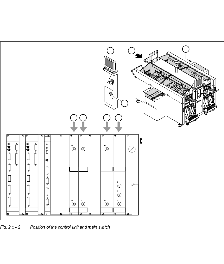
1. Main switch 2. Service socket behind the safety doors
3. Compressed air unit 4. Servo unit
5. Measuring unit in the servo unit
1. Main switch 2. Control unit
3. Power supply unit ± 12 VDC 4. Power supply unit ± 15 VDC
5. Power supply unit + 5 VDC/+ 24 VDC 6. Power supply unit + 5 VDC/+ 50 VDC
4
A
A
2
1
X2sv
GEM
+ 5V+ 24 V- 15 V- 12 V
X1sv
MC
3,8V
+ 48V+ 5 V
X4sv
ICOS 2
X3sv
ICOS 1
+ 15 V+ 12 V
S-COM 1
X4st
X4su
S-COM 1
X7su
X7st
X6su
X9su
AUX
AUX
X6st
X9st
Abort
Reset
S-COM 2
X3st
X8su
X3su
S-COM 2
X5su
VGA
VGA
HS3L
Reset
Abort
HS3L
X5st X8st
Batterie
Kamera 1/3
Kamera 1/3Kamera 2/4
Kamera 2/4
3 65
X4teX4tdX4tbX4ta
X3te(GND)
X5te
X3tdX3tbX3ta
User Manual HS-50 2 Operational Safety
Software-Version 5.01Edition 01/99 2.5 Energy state of the placement system after switching off at the main switch
77
0DLQVZLWF KVZLWFKHGRIISODFHPHQWV\V WHPFRQQHF WHGWRWKHPDLQSRZH U
VXSSO\
The following table shows the voltages of the individual modules when the main switch is switched
off, but the placement system is still connected to the main power supply.
DANGER
The following components still carry potentially lethal voltages even if the main switch is switched
off:
– cable connection terminals 1, 3, and 5 of S1 main switch
– Z1 main power filter
– BU1 service socket
– F1 automatic circuit breaker for the service socket
– The color of all individual wires, which still carry potentially lethal voltages even if the main
switch is switched off is brown.
0RGXOH 9ROWDJH
Z1 main power filter
Cable connection terminals L1, L2, L3
3 x 204 VAC
3 x 400 VAC
3 x 460 VAC
BU1 service socket
115 VAC
230 VAC
265 VAC
F1 automatic circuit breaker
115 VAC
230 VAC
265 VAC
S1 main switch
Cable connection terminals 1, 3, 5
3 x 204 VAC
3 x 400 VAC
3 x 460 VAC
Servo unit (see item 5 of diagram)
Test socket X2
Test socket X3
Test socket X4
GND X1
< 10 VDC
< 10 VDC
< 10 VDC

2 Operational Safety User Manual HS-50
2.5 Energy state of the placement system after switching off at the main switch Software-Version 5.01 Edition 01/99
78
0DLQVZLWFKVZLWFKHGRIISODFHPHQWV\VWHPGLVFRQQHFWHGIURPWKHSRZHU
VXSSO\
The placement system is de-energized, apart from slight residual voltages in the servo unit.
&RPSUHVVHGDLUFRQGLWLRQVLQWKHSODFHPHQWV\VWHPDIWHUVZLWFKLQJRIIDWWKH
PDLQVZLWFK
When the placement system is switched off at the main switch (item 1 in the diagram) or the power
supply to the placement system fails, the electrically-controlled main valve Y1 shuts off the com-
pressed air unit (item 3 in the diagram). The pressure drops to 0 bar within 5 seconds.
Control unit (see items 3, 4, 5 and 6)
Test socket + 12 VDC (x3ta)
Test socket - 12 VDC (x4ta)
Test socket + 15 VDC (x3tb)
Test socket -15 VDC (x4tb)
Test socket + 5 VDC (x3td)
Test socket + 24 VDC (x4td)
Test socket + 50 VDC (x5te)
Test socket + 5 VDC (x4te)
GND (x3td)
0 VDC
0 VDC
0 VDC
0 VDC
0 VDC
0 VDC
0 VDC
0 VDC