00191369-01.pdf - 第81页
User Manual HS-50 2 Operational Safety Software-Version 5.01Edition 01/99 2.6 Lock out and tag out procedure when perform ing any maintenance work or service work 79 /RFNRXWDQGW DJRXWSURFHGXUHZ KHQSHUIRUPLQJ …

2 Operational Safety User Manual HS-50
2.5 Energy state of the placement system after switching off at the main switch Software-Version 5.01 Edition 01/99
78
0DLQVZLWFKVZLWFKHGRIISODFHPHQWV\VWHPGLVFRQQHFWHGIURPWKHSRZHU
VXSSO\
The placement system is de-energized, apart from slight residual voltages in the servo unit.
&RPSUHVVHGDLUFRQGLWLRQVLQWKHSODFHPHQWV\VWHPDIWHUVZLWFKLQJRIIDWWKH
PDLQVZLWFK
When the placement system is switched off at the main switch (item 1 in the diagram) or the power
supply to the placement system fails, the electrically-controlled main valve Y1 shuts off the com-
pressed air unit (item 3 in the diagram). The pressure drops to 0 bar within 5 seconds.
Control unit (see items 3, 4, 5 and 6)
Test socket + 12 VDC (x3ta)
Test socket - 12 VDC (x4ta)
Test socket + 15 VDC (x3tb)
Test socket -15 VDC (x4tb)
Test socket + 5 VDC (x3td)
Test socket + 24 VDC (x4td)
Test socket + 50 VDC (x5te)
Test socket + 5 VDC (x4te)
GND (x3td)
0 VDC
0 VDC
0 VDC
0 VDC
0 VDC
0 VDC
0 VDC
0 VDC

User Manual HS-50 2 Operational Safety
Software-Version 5.01Edition 01/99 2.6 Lock out and tag out procedure when performing any maintenance work or service work
79
/RFNRXWDQGWDJRXWSURFHGXUHZKHQSHUIRUPLQJ
DQ\ PDLQWHQ DQFHZRUNRUVHUYLF HZRUN
3XUSRVHDQGVFRSH
Before performing any maintenance work or service work, a procedure of locking and tagging
must be followed. The procedure, when followed correctly eliminates the possibility of an em-
ployee being injured.
NOTE
These procedures represent the minimum lock/tag out requirements. Any additional safe-guards
needed to complete work safely can be specified by facilities supervision, the safety officer, the
safety committee and the health department.
'HVFULSWLRQ
Whenever it becomes necessary to isolate, control and release energy, the following procedure is
to be followed
1. Notify affected employees.
2. Shut down equipment, using normal stopping procedures, such as
– depressing the stop button
– shutting down the station computer or
– switching off the placement system at the main switch.
3. Isolate the equipment from all its energy sources such as
– compressed air supply and
– power supply.
4. Lock Out equipment.
– Apply the lock and the lockout whenever possible.
2 Operational Safety User Manual HS-50
2.6 Lock out and tag out procedure when performing any maintenance work or service work Software-Version 5.01 Edition 01/99
80
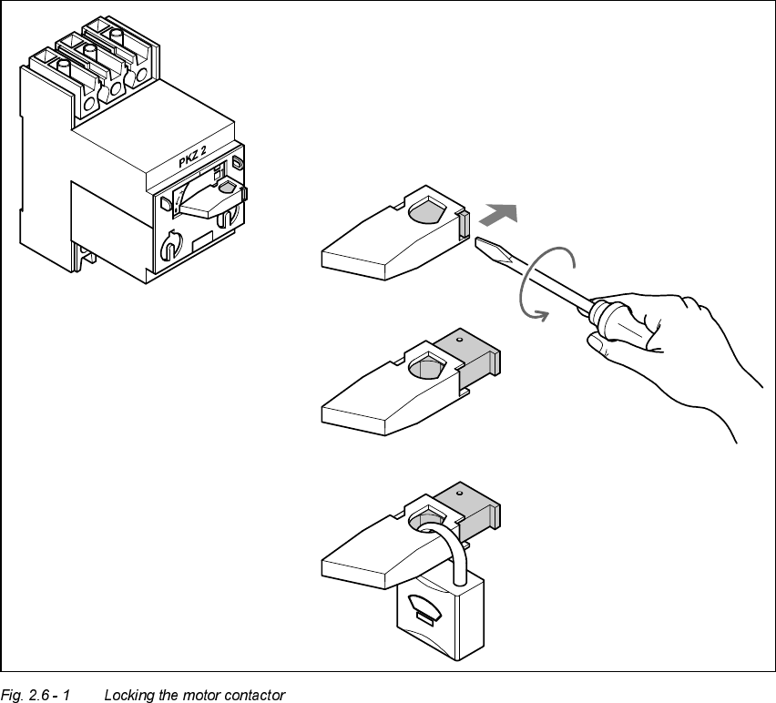
1. Turn the operating lever (1) counter-clockwise.
2. Use the screwdriver to push the locking lug (2) out of the operating lever (1).
3. Secure the operating lever with a padlock (3).
– The Tag Out alternative:
If a machine can be locked out, it must be. However, there are situations where energy iso-
lating devices can not accommodate locks. In these cases, the energy isolating devices must
be tagged to warn employees that the machine is de-energized for servicing. The tag must be
securely fastened, it must be placed in a position visible to all and it may only be removed by
the person who attached it.