00191369-01.pdf - 第89页
User’s Manual SIPLACE HS-50 3 Introduction and Basic Concepts Software Vers ion SR.501.xx E dition 01/99 3.1 Mac hine Displays and Controls 87 * HQHUDO Every statio n is equi pped wi th a "station computer &…
3 Introduction and Basic Concepts User’s Manual SIPLACE HS-50
3.1 Machine Displays and Controls Software Version SR.501.xx Edition 01/99
86
0DFKLQH'LVSOD\VDQG&RQWUROV
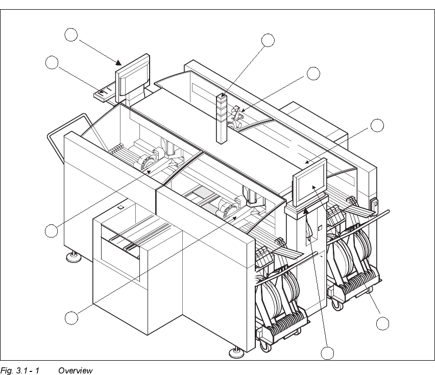
2YHUYLHZ
.H\WR)LJ
(1) Monitor (left side)
(2) Keyboard (left side)
(3) Gantry 4
(4) Gantry 1
(5) Keyboard (right side)
(6) Monitor (right side)
(7) Gantry 2
(8) Gantry 3
4
2
1
9
6
5
3
8
7

User’s Manual SIPLACE HS-50 3 Introduction and Basic Concepts
Software Version SR.501.xx Edition 01/99 3.1 Machine Displays and Controls
87
*HQHUDO
Every station is equipped with a "station computer". The station computer is located on the
side of the input area behind a machine base door. This area also accommodates the
uninterruptible power supply (UPS).
A monitor with touch screen and sliding keyboard with integrated trackball is mounted on
either side of the station (see Figure 3.1 - 1).
NOTE
You can operate the SR software interface either via the keyboard and trackball or via the
touch screen (see section 3.2.1).
The position of the switches and buttons (main switch, key-operated switches, start/stop
button, EMERGENCY STOP button etc.) is illustrated in Figure 3.1 - 3. The functions are
described in Chapter 2.
WARNING
The machine base doors may only be opened by qualified personnel since certain machine
components carry hazardous voltages.
The relevant accident prevention and applicable regulations regarding electrical/electrome-
chanical installations must be strictly complied with. Failure to do so may result in death,
severe physical injury or considerable damage to property.
3 Introduction and Basic Concepts User’s Manual SIPLACE HS-50
3.1 Machine Displays and Controls Software Version SR.501.xx Edition 01/99
88
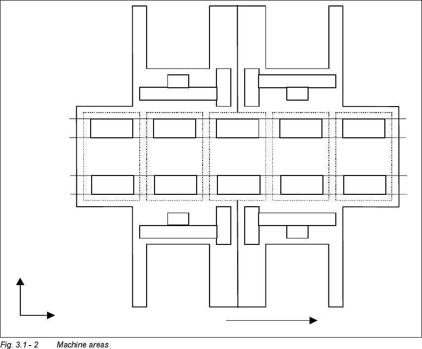
0DFKLQH$UHDV
The figure below provides a diagrammatic overview of the individual areas of a
SIPLACE HS-50 placement station.
The terms used in the figure to describe these areas are also used in the texts in the user
interface and in the User’s Manual.
([SODQDWLRQRI7HUPV
PA = processing area (1 or 2)
The conveyor is subdivided into the following sections in accordance with the machine
areas:
Input conveyor => Processing conveyor 1 => Intermediate conveyor => Processing
conveyor 2 => Output conveyor
Input
area
PA1 PA2
Output
area
Intermediate
area
Location 1 Location 2
Location 4 Location 3
Gantry 1
Gantry 3
Gantry 2
Gantry 4
Direction of transport
Conveyor 1
(right)
Conveyor 2
(left)
+X
+Y