00191369-01.pdf - 第44页
1 Introduction User Manual HS-50 1.13 Overview of the modules - revolver head Software Version 5.01 01/99 Issue 42 All the c omponents ar e inserted with the same cycle tim e. Befo re the co mponen t is inser ted, it is …
User Manual HS-50 1 Introduction
Software Version 5.01 01/99 Issue 1.13 Overview of the modules - revolver head
41
2YHUYLHZRIWKHPRGXOHVUHYROYHUKHDG
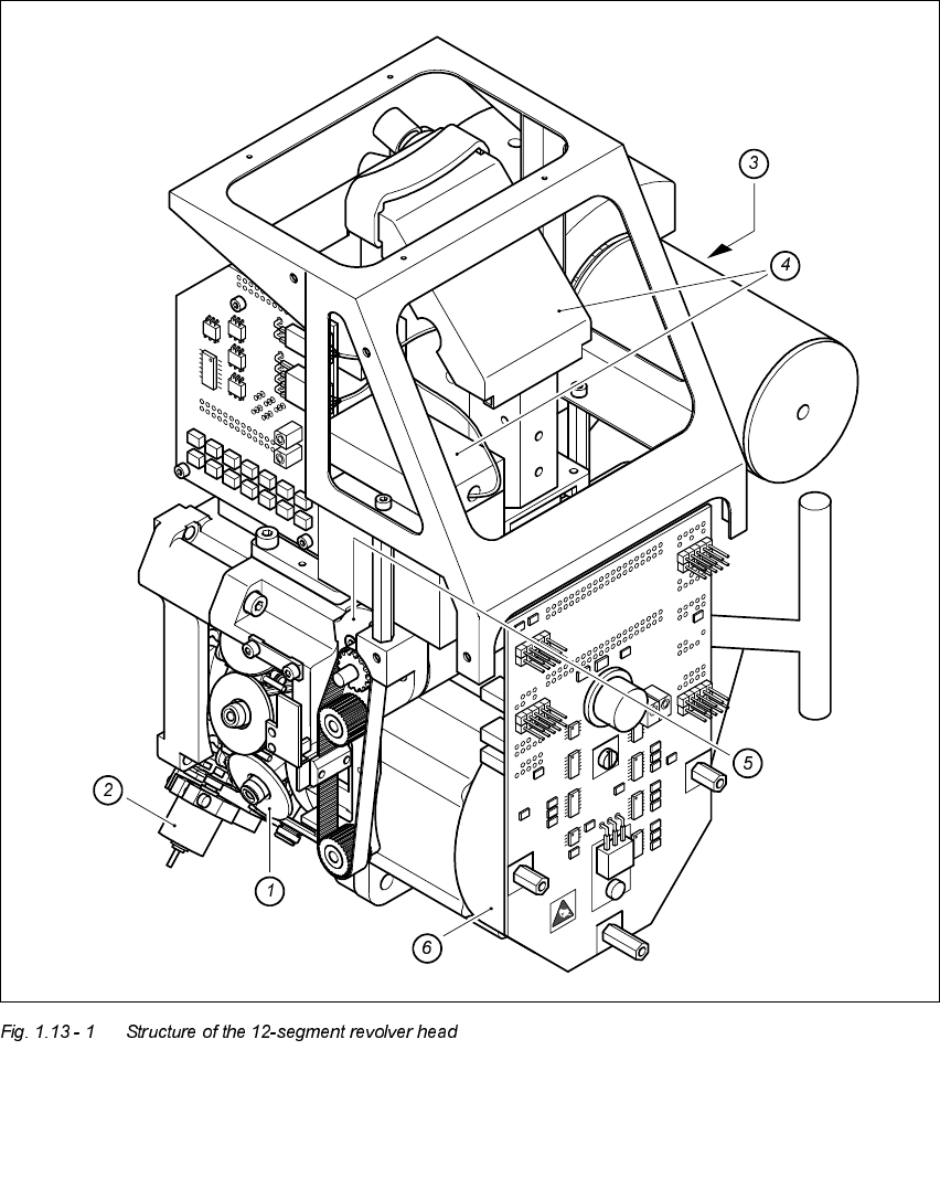
6WUXFWXUHRIWKHVHJPHQWUHYROYHUKH DG
1. Star with 12 sleeves 4. Component vision system
2. Motor for "Reject" valve adjustment drive 5. Z axis drive
3. Turning station 6. Star motor

1 Introduction User Manual HS-50
1.13 Overview of the modules - revolver head Software Version 5.01 01/99 Issue
42
All the components are inserted with the same cycle time. Before the component is inserted,
it is measured by the optoelectronic vision system.
– The component vision camera creates an image of the current component.
– The precise position of the component is also determined.
– The package form of the current component is compared against the programmed pack-
age form in order to identify it. Any components that cannot be identified are rejected.
– The turning station turns the component to the required placement position.
'HVFULSWLRQRIWKHVHJPHQWUHYROYHUKHDG
– The 12-segment revolver head works using the "collect & place" principle, i.e. the compo-
nents are held by the nozzles with the aid of a vacuum and, after one complete pick-up cy-
cle, are placed gently and accurately on the PCB with the aid of forced air. The vacuum in
the nozzles is also checked several times to determine whether the components were
picked up and set down correctly.
– The "adaptive" sensor stop mode of the z axis compensates for any irregularity of the PCB
surface when the components are set down.
– Defective components are rejected and are picked up again during a repair run.
7HFKQLFDOGDWDUHYROYHUSODFHPHQWKHDG
Range of components
0402 to PLCC44, including BGA, µBGA, flip-chip,
TSOP, QFP, PLCC, SO to SO32, DRAM
Maximum height 6 mm
Minimum lead pitch 0.5 mm
Minimum dimensions 0.5 mm x 1.0 mm
Maximum dimensions 18.7 mm x 18.7 mm
Maximum weight 2 g
Maximum travel of the z axis 16 mm
Programmable set-down force 2.4 to 5.0 N
Nozzle types 7xx
Benchmark placement speed 12,500 components/hour
Angular accuracy 0.7° at 4 sigma
Placement accuracy ± 90 µm at 4 sigma
± 135 µm at 6 sigma

User Manual HS-50 1 Introduction
Software Version 5.01 01/99 Issue 1.14 Overview of the modules - vision systems
43
2YHUYLHZRIWKHPRGXOHVYLVLRQV\V WHPV
Each placement system has
– four component vision cameras on the placement heads and
– four PCB vision cameras on the underside of the x axis gantries.
The vision evaluation units are located in the control unit for the placement system and the
component vision system is used to determine:
– the precise position of the components at the nozzle and
– the geometry of the package form.
The PCB vision system uses fiducials on the PCBs to determine:
– the position of the PCB,
– its rotation angle
– and the PCB delay.
The PCB vision system also uses fiducials on the feeder modules to determine the exact pick-
up position of components, which is particularly important for small components.
7HFKQLFDOGDWDFRPSRQHQWYLVLRQPRGXOHRQWKHVHJPHQWUHYROYHU
KHDG
Maximum component dimensions 18.7 mm x 18.7 mm
Range of components 0402 to PLCC44
including BGA, µBGA, flip-chip, TSOP, QFP
PLCC, SO to SO32, DRAM
Lead spacing > = 0.5 mm
Field of vision 24 mm x 24 mm
Illumination method Front-lighting (3 levels programmable as required)