00191369-01.pdf - 第23页
User Manual HS-50 1 Introduction Software Vers ion 5.01 01/99 Issue 1.5 Description of the machine 21 'HV FULSWLRQRI WKHPDFKLQH )XQFWLRQDOGHVFULSWLRQ The automati c place ment sys tem is a high-pe rfor…

1 Introduction User Manual HS-50
1.4 Revision index Software Version 5.01 01/99 Issue
20
6HUYLFHHQJLQHHUV
This class is reserved for Siemens engineers, who are trained to carry out servicing work and
to upgrade and retrofit the placement system.
WARNING A thorough knowledge of the relevant part of this User Manual is
required before carrying out any work on the machine. All work must be carried out by appro-
priately trained and qualified personnel. All warning, caution and danger notes MUST be ob-
served.
PLEASE NOTE: The content of this User Manual is not part of or intended to modify a previous
or existing agreement, undertaking or legal relationship. Any undertakings entered into by Si-
emens AG result from the purchase contract, which also contains complete and generally ap-
plicable guarantees. Such contractual guarantee provisions are neither extended nor
restricted by the information given in this User Manual.
5HYLVLRQLQGH[
0DQXDO 6RIWZDUHYHUVLRQ ,VVXH
First draft HS-50 Provisional User Manual 5.01 09/98
Revision of HS-50 User Manual 5.01 01/99
User Manual HS-50 1 Introduction
Software Version 5.01 01/99 Issue 1.5 Description of the machine
21
'HV FULSWLRQRIWKHPDFKLQH
)XQFWLRQDOGHVFULSWLRQ
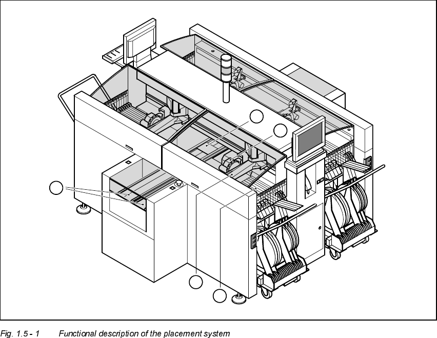
The automatic placement system is a high-performance placement system with four gantry
axis systems. A PCB vision system and a star-shaped 12-segment revolver head are mounted
on each gantry. Revolver placement heads equipped with a component vision system pick up
the components from stationary feeder modules and insert them into the PCB clamped in the
PCB conveyor.
1. 12-segment revolver placement head with component vision camera
2. Gantry axis system with PCB vision camera
3. Stationary component feeder
4. Clamped PCB
5. PCB conveyor (dual conveyor option)
3
5
2
4
1

1 Introduction User Manual HS-50
1.5 Description of the machine Software Version 5.01 01/99 Issue
22
The concept behind the automatic placement system
– with its stationary feeder modules,
– PCBs that do not move during placement
– and positionable placement heads
has a number of significant benefits:
– For example, the flexible 12-segment revolver heads combined with automatic nozzle
changers enable the nozzle configuration to be changed temporarily and automatically
adapted to receive different component sizes. You can also optimize the traversing paths
and the placement sequence.
– With stationary feeder modules, even the tiniest components are picked up reliably.
– The components cannot slip on the PCB during placement (as is often the case with mov-
ing PCBs) since the PCB does not move.
– Sophisticated optical centering systems (vision systems) for components and PCBs also
ensure high component positioning accuracy.
– Components can be topped up and tapes can be spliced without stopping the machine.
– Prepared component tables enable the placement system to be retooled without long stop-
pages.
7HFKQLFDOGDWDPDF KLQHRYHUYLHZ
Range of components From 0402 to PLCC44, SO32, DRAM
Maximum placement speed of the12-segment
revolver head 50,000 components/hour
Cycle time at the revolver head 125 ms, regardless of the type of component
Accuracy ± 90 µm at 4 sigma
± 135 µm at 6 sigma
PCB format 50 x 50 mm to 368 x 460 mm
2" x 2" to 14.5" x 18"
Feeding capacity Up to 96 tracks, each with 8 mm tapes
Feeder modules Tapes, bulk-cases
Operating system Microsoft Windows NT / RMOS
Combination options Inline or stand-alone
Space required 7.5 m² / module